EU and EW Series Valves
Instruction Manual
August 2010
21
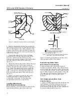
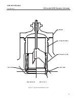
2. Orient the Bore Seal plug seal for correct sealing
action based on the process fluid flow direction
through the valve.
D
The open interior of the Bore Seal plug seal
must face up in a valve with flow-up construction
(figure 10).
D
The open interior of the Bore Seal plug seal
must face down in a valve with flow-down
construction (figure 10).
3. Place the Bore Seal plug seal over the top of the
valve plug. The retainer will help guide the Bore Seal
down onto the plug. Do not force the Bore Seal over
the plug. For flow down constructions, skip to step 5.
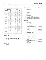
4. An installation tool (see table 5) must be inserted
into the Bore Seal prior to using the retainer to guide
it down the plug.
5. Apply a suitable high-temperature lubricant to the
threads on the plug. Then, place the Bore Seal
retainer onto the plug and tighten the retainer using
an appropriate tool such as a strap wrench. For flow
down constructions, skip to step 7.
6. Remove the retainer and then the installation
tool. Place the Bore Seal retainer back onto the plug
and tighten the retainer using an appropriate tool
such as a strap wrench.
7. Using an appropriate tool such as a center
punch, stake the threads on top of the plug in one
place (figure 12) to secure the Bore Seal retainer.
8. Replace the piston ring(s) following instructions in
the Trim Replacement section of this manual.
9. Return the seat ring, cage, plug/retainer
assembly, and stem to the valve body and
completely reassemble the valve package following
the appropriate instructions in the Trim Replacement
section of this manual.
CAUTION
To avoid excessive leakage and seat
erosion, the valve plug must be
initially seated with sufficient force to
overcome the resistance of the Bore
Seal and contact the seat ring. You can
correctly seat the valve plug by using
the same force calculated for full load
when sizing your actuator. With no
pressure drop across the valve, this
force will adequately drive the valve
plug to the seat ring, thus giving the
Bore Seal a predetermined permanent
set.
With full actuator force applied and the
valve plug fully seated, align the
actuator travel indicator scale with the
lower end of valve travel. Refer to the
appropriate actuator instruction
manual for information on this
procedure.
Parts Ordering
Each body-bonnet assembly is assigned a serial
number, which can be found on the valve. This same
number also appears on the actuator nameplate
when the valve is shipped from the factory as part of
a control valve assembly. Refer to the serial number
when contacting your Emerson Process
Management sales office for technical assistance.
When ordering replacement parts, refer to the serial
number and to the key number and part name from
the following list. Specify the desired material, if
known. Part numbers are shown for packing box
parts. Specify the part number if you are ordering
packing parts.
WARNING
Use only genuine Fisher replacement
parts. Components that are not
supplied by Emerson Process
Management should not, under any
circumstances, be used in any Fisher
valve, because they may void your
warranty, might adversely affect the
performance of the valve, and could
cause personal injury and property
damage.
Note
Neither Emerson, Emerson Process
Management, nor any of their affiliated
entities assumes responsibility for the
selection, use, or maintenance of any
product. Responsibility for the
selection, use, and maintenance of any
product remains with the purchaser
and end user.


