background image

32

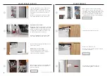
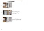
FLUSH WATER THROUGH THE WATER DISPENSER

FLUSH WATER THROUGH THE ICE MAKER

Press the water dispenser pad and 
dispense a total of 8 Litres of water.
A harmless carbon residue may be 
dispensed with the water during 
this process.

Press 

Fridge

3.0 °C

Fridge

3.0 °C

Fridge

5.0 °C

 to display the menu. 

Ensure power and water connections 
have been turned on.

Ensure power and water connections 
have been turned on.

When dispensing for long durations, a 
time out period may occur where an 
alarm will sound. Please wait 2 minutes 
before dispensing again.

Press 

Fridge

3.0 °C

Fridge

3.0 °C

Fridge

5.0 °C

 or 

Fridge

3.0 °C

Fridge

3.0 °C

Fridge

5.0 °C

 to scroll through the list 

and select 

ICE

Press 

Fridge

3.0 °C

Fridge

3.0 °C

Fridge

5.0 °C

 to turn ice maker on.

The flushing process will be complete 
after the first full bin of ice is produced. 
We recommend discarding this batch of 
ice as it may appear slightly discoloured 
and contain a harmless carbon residue. 

1

1

2

2

3

3

4

Setup

Wi-Fi

Settings

4.0°C

-18.0°C

Fridge

Freezer

Ice

ON

Summary of Contents for RS6019F2L

Page 1: ...INTEGRATED RS6019S2R RS6019F2L RS6019S3RH and RS6019F3LJ models INTEGRATED REFRIGERATION INSTALLATION GUIDE NZ AU UK IE SG HK...

Page 2: ......

Page 3: ...be installed by a professional installer according to the installation steps in this guide SAFETY AND WARNINGS WARNING 420 630 lb 190 285 kg Weight Hazard Failure to follow this advice may result in...

Page 4: ...an isolation valve is available if water connection is not accessible z Contact an electrical and or a plumbing professional if you are uncertain the electrical and or plumbing conditions for installa...

Page 5: ...UI RS60 non Hinge RH Trim UI RS60 Hinge LH Trim UI RS60 non hinge LH Trim UI RS60 Hinge RH Assy hinge spacer A Cover hinge spacer A Install kit B Kit hinge spacer depth gauges Assy hinge spacer B Cove...

Page 6: ...tely for multiple installation Water filter comes fitted to product Bracket dual connection top Screw M5X12 CSKPH NP Bracket duel plinth FNT 1X Screw M5X12 PH MT STL ZN Screw 8GX16 mush washer HD Trim...

Page 7: ...andle 1 M5x25 Hex screw 2 Round flush handle 1 M5x25 Hex screw 2 MODEL DESCRIPTION AHSRDSF Round Handle Kit Round handle set Square Fine handle set Professional round flush handle set MODEL DESCRIPTIO...

Page 8: ...T25 Spanner Supplied tools Required tools Not supplied and must be provided by the installer M4 Ball allen key Powered driver Hand truck Cross head screwdriver Flathead screwdriver Cutter Socket 8mm M...

Page 9: ...om top of door panel 3 G Height of door panel 1775 H Depth of door panel 19 I Height from floor to bottom of door panel 102 J Depth of toe kick excl front door and toe kick panels 50 100 Cavity Dimens...

Page 10: ...ensions mm I Overall height of cavity 1880 J Overall width of cavity 600 K Minimum overall depth of cavity When services are located outside of cavity shallow When services are located in the cabinet...

Page 11: ...ctrical Plumbing Supply Dimensions mm d Overall height of supply routing area at rear of cavity 37 Overall width of supply routing area at rear of cavity 600 E Overall depth of supply routing area at...

Page 12: ...cabinet Hose and Cord Lengths mm Electrical a Power cord length from the left edge of the product 1800 B Power cord length from the right edge of the product 2000 C Power cord length from the top of t...

Page 13: ...E Height from floor to bottom of door panel 15 150 F Height of toe kick panel 100 G Width of toe kick panel 597 Maximum weight of door panel 19kg Custom door panel handle and toe kick panel to be manu...

Page 14: ...d Dwg Dxf Files Dwg and Dxf files of the panel preparation can be downloaded from Trade Resources www fisherpaykel com Template A template for marking and drilling the holes is provided with the produ...

Page 15: ...to open at the same time 100 Minimum Door Clearance Vertical Gap mm F Dual Install Stainless steel door panels gaps equalized during installation 5 Custom panels width of custom panel increased to ma...

Page 16: ...o be installed alongside the anti tip bracket Refer to page 18 for details Ensure a finished return has been created 1 2 3 4 Ensure services are accessible and correctly installed Refer to Services fo...

Page 17: ...t and set aside Remove the two remaining transit brackets Check levelling feet have been raised tilt product and insert handtruck Restrain product to handtruck We recommend using the corner posts to p...

Page 18: ...ward when the door is opened Check for wall stud 1 5 For solid wall installs Using the bracket as a guide pre drill four holes into the wall or spacer Secure bracket using crosshead screws Install kit...

Page 19: ...top cover 6 4 Use a flathead screwdriver to remove the inside plates Move to the other side ensuring the rounded corners face the inside Slot the door back onto the screws and tighten using a torx key...

Page 20: ...re the bracket at the front base using four screws Joiner kit A Secure the bracket at the rear base using four screws Joiner kit A Secure the bracket at the front top using four screws Joiner kit B 6...

Page 21: ...fit the depth gauges at the the top bottom of the door as shown Install kits B C Clip both hinge spacers onto the product Ensure spacer A is fitted to the top of the product and spacer B is fitted to...

Page 22: ...e and power cord to bring any slack inside the plinth and reduce the risk of them tangling behind the product Push product into alcove while pulling the hose and power cord Ensure the gauges touch the...

Page 23: ...check for leaks Push product into alcove Push in until the gauges touch the alcove end Ensure hose doesn t bend or kink and that the power cord is not trapped If required wrap a thread around the hose...

Page 24: ...crew to adjust the rear of the product followed by the lefthand screw to adjust the front Turn clockwise to raise and anti clockwise to lower Ensure feet engage with the floor and the upper bracket to...

Page 25: ...gn the centre door panel bracket to panel ensuring the V in bracket is to sit on the centreline Using the screws supplied in the install kit secure the door panel bracket using seven screws 5 6 Secure...

Page 26: ...3 4 Determine the panel orientation based on the hinge and handle positions Red labels indicate left hinge installations blue labels indicate right hinge installations Remove all blue tape from the pa...

Page 27: ...ets are disengaged and the top mounting screws have been loosened Rotate the mounting studs clockwise to lower the panel and anticlockwise to raise it Push panel side to side to adjust horizontally En...

Page 28: ...f the product and slide down to clip in place If a gap is present remove and readjust the side brackets Fit the top cover using two screws Ensure flat side faces out from the panel Locate the longer d...

Page 29: ...grille to secure Fit the top UI trim taking into account the hinge location Install kit H FIT TRIMS AND GRILLE Locate trim between products Lower trim before pushing in to ensure bottom connector brac...

Page 30: ...ick panel Install kit E SECURE TOE KICK Slide both depth adjustment brackets all the way forward and slightly tighten the screws Loosen the screws on both toe kick depth adjustment brackets Attach the...

Page 31: ...step by step guidance on both your appliance and mobile device z It may take up to 10 minutes to connect your appliance 1 2 3 4 Press Fridge 3 0 C Fridge 3 0 C Fridge 5 0 C to display the menu Press...

Page 32: ...When dispensing for long durations a time out period may occur where an alarm will sound Please wait 2 minutes before dispensing again Press Fridge 3 0 C Fridge 3 0 C Fridge 5 0 C or Fridge 3 0 C Fri...

Page 33: ...n adjusted and engaged If water is turned on purge before first use All panel gaps and any potential clashing points have been checked All covers are in place Product is robustly attached to cabinetry...

Page 34: ...move from alcove Ensure doors are taped shut and safe handling practices are observed 1 2 3 SAFE PRODUCT REMOVAL Remove the flow divider and panel bracket before removing all door panel side screws an...

Page 35: ...ge at any time The product specifications in this guide apply to the specific products and models described at the date of issue Under our policy of continuous product improvement these specifications...

Reviews: