


840653
47
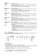
•
The 3
rd
LED from the left indicates that the condenser fan is on.
•
The 2
nd
LED from the right indicates that the auxiliary heater is on.
•
The right hand LED indicates that the defrost heater is on.
6.
To return to normal operation, press and hold the
LOCK
button, then within 1 second press the
FUNCTION SELECT
button. Hold for 3 seconds.
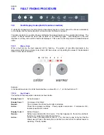
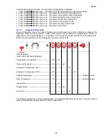
10.1.4.9 Last
Fault
1 2
To read the Last Fault:
1.
Open the drawer.
2. Press
the
LOCK
button for 3 seconds to unlock the control panel.
3.
Within 15 seconds, press and hold the
LOCK
button, then within 1 second press the
FUNCTION
SELECT
button. Hold for 3 seconds.
4. Press
the
WARMER
button eight times.
5.
The Pantry LED will be illuminated. The Last Fault is displayed in a Binary code form in the
temperature indicator LEDs (refer to Section 10.1.1).
6.
To return to normal operation, press and hold the
LOCK
button, then within 1 second press the
FUNCTION SELECT
button. Hold for 3 seconds.
Note:
The last fault is cleared from the memory after the next defrost.
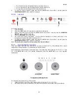
10.1.5
Sensor Temperature Conversion
If the red Freezer LED plus one other LED is on (refer to Section 10.1.4), this indicates that a sensor
temperature is being displayed. Temperatures are read as follows:
Each temperature scale LED has a numerical value. The values from left to right are: 32, 16, 8, 4, 2, 1 and
0.5. If the
LOCK
LED is off, it is a positive temperature, and if the
LOCK
LED is on, it is a negative
temperature.
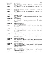
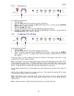
Temperature Binary Code
To obtain the temperature of any of the sensors:
1.
Obtain the binary code of the sensor reading (refer to Sections 10.1.4 to 10.1.4.6).
2.
Add up the binary number indicated by the temperature indicator LED pattern (see Figure above).
Flashing
32
16
8
4
2
1
0.5
Summary of Contents for RB36S25MKIW
Page 1: ...840653 Service Manual CoolDrawer Models RB36S25MKIW RB90S64MKIW ...
Page 12: ...840653 12 3 4 Integrated Panel Preparation ...
Page 14: ...840653 14 3 5 Create Cut Outs In Frame 3 6 Locate And Secure Install Brackets ...
Page 15: ...840653 15 3 7 Attach Inlet And Outlet Vent Ducts 3 8 Attach Power Cord And Trim Brackets ...
Page 16: ...840653 16 3 9 Move Product Into Cavity 3 10 Fit Drawer Panel Attachment Hooks ...
Page 17: ...840653 17 3 11 Attach Drawer Panel To Front Of Drawer ...
Page 18: ...840653 18 3 12 Secure Trim Brackets To Cabinetry 3 13 Attach Trims To Sides Of Cabinetry ...
Page 19: ...840653 19 3 14 Attach False Panel 3 15 Check Operation ...
Page 53: ...840653 53 11 WIRING DIAGRAMS Ω Ω Ω Ω Ω Ω Ω Ω Ω Ω ...
Page 54: ...840653 54 ...
Page 77: ...840653 77 ...


