


840653
40
10
FAULT FINDING PROCEDURE
10.1
Fault Display Codes (Both Visual And Audible)
If a fault should develop in the temperature measurement system, a fault code will be shown automatically
on the display and the fault audio alarm will sound when the drawer is opened.
The alarm consists of a number of beeps emitted by the beeper located on the power/control module. The
number of beeps indicate the fault code as listed on the following pages. Also displayed on the user
interface is a binary code with the fault code displayed. This is seen in the temperature increase/decrease
LEDs.
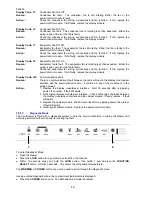
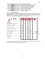
10.1.1
Binary Code
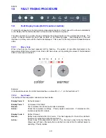
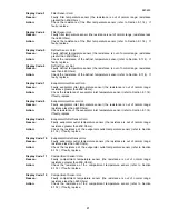
When a fault occurs, the fault (spanner) LED is flashing. The pattern of red LEDs illuminated in the
temperature LEDs forms a binary code. Each LED has a value, and by adding the values of the illuminated
LEDs, a total value is obtained.
Example:
In the illustration above, the LEDs illuminated have a value of 8 + 2 + 1, so the fault code is 11.
10.1.2
Fault Codes
The faults and their respective codes are as shown below.
Display Code: 0
No faults present.
Display Code: 1
Compressor Can’t Start.
Reason:
The compressor has failed to start after 6 attempts.
Action:
Check the compressor windings. If faulty, replace compressor. If compressor O.K.,
replace power/control module.
Display Code: 2
Defrost Timeout.
Reason:
Defrost was aborted after 40 minutes. This has happened in the last two defrosts,
therefore it is probably a defrost heater failure.
Action:
Check to see if the evaporator is iced up. If so, this may be due to the fact that the
drawer was left open. Manually force a defrost and check that the defrost heater is
operating. If faulty, replace.
64 32
16
8
4
2
1
Summary of Contents for RB36S25MKIW
Page 1: ...840653 Service Manual CoolDrawer Models RB36S25MKIW RB90S64MKIW ...
Page 12: ...840653 12 3 4 Integrated Panel Preparation ...
Page 14: ...840653 14 3 5 Create Cut Outs In Frame 3 6 Locate And Secure Install Brackets ...
Page 15: ...840653 15 3 7 Attach Inlet And Outlet Vent Ducts 3 8 Attach Power Cord And Trim Brackets ...
Page 16: ...840653 16 3 9 Move Product Into Cavity 3 10 Fit Drawer Panel Attachment Hooks ...
Page 17: ...840653 17 3 11 Attach Drawer Panel To Front Of Drawer ...
Page 18: ...840653 18 3 12 Secure Trim Brackets To Cabinetry 3 13 Attach Trims To Sides Of Cabinetry ...
Page 19: ...840653 19 3 14 Attach False Panel 3 15 Check Operation ...
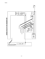
Page 53: ...840653 53 11 WIRING DIAGRAMS Ω Ω Ω Ω Ω Ω Ω Ω Ω Ω ...
Page 54: ...840653 54 ...
Page 77: ...840653 77 ...


