


840653
33
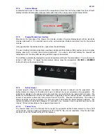
8.1.4
Cabinet Module
Located behind a cover on the rear wall of the compartment, this is the hub for feed back from the soft touch
display module and compartment drawer reed switch and is the power source for the drawer LEDs.
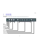
8.1.5
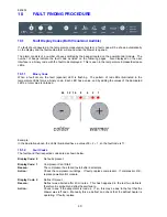
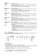
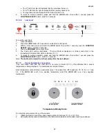
Display Module/User Interface
Mounted on the top edge of the drawer, this module consists of a glass display panel with an electronic
module underneath it. It is controlled via a 4-wire communications interface connected from it to the cabinet
module.
Using signals from the cabinet module, it generates the LED display.
The user interface contains capacitance switches and light-emitting diodes (LEDs) and has icons on a glass
display panel with a printed circuit board underneath. It is used to input and display the required set
temperatures for the compartments along with the usage mode selected.
The interface automatically displays the current temperature setting for the compartment. This is shown as a
series of LED lights. To adjust the temperature, simply press the temperature
COLDER
or
WARMER
buttons to achieve the required setting.
8.1.6
Defrost Heater
Located as part of the fin-on-tube evaporator, the defrost element is clipped onto the evaporator. The
defrost element is rated at 200 watts and is used to defrost the ice accumulated on the evaporator. The
defrosts are adapted to the usage and environment and are controlled by the power/control module. The
defrost is terminated when any of the evaporator compartment sensor (defrost sensor, evaporator inlet
sensor or evaporator outlet sensor) are greater than +8
O
C (46
O
F). Previous defrost history, the number of
drawer openings, and the compressor run time are used to determine the interval between defrosts. The
typical time interval for defrosts is between 12 hours and 1 day. However it can be as short as 6 hours or as
long as 106 hours depending on the usage and environment.
8.1.6.1 Thermal
Fuse
The thermal fuses are in the harness that connects the evaporator defrost heater element to the air bell
wiring socket. Having a tripping temperature of 72
O
C (162
O
F), they are not resettable. If the thermal fuses
are open circuit, the harness will need to be replaced.
Cabinet Module
Summary of Contents for RB36S25MKIW
Page 1: ...840653 Service Manual CoolDrawer Models RB36S25MKIW RB90S64MKIW ...
Page 12: ...840653 12 3 4 Integrated Panel Preparation ...
Page 14: ...840653 14 3 5 Create Cut Outs In Frame 3 6 Locate And Secure Install Brackets ...
Page 15: ...840653 15 3 7 Attach Inlet And Outlet Vent Ducts 3 8 Attach Power Cord And Trim Brackets ...
Page 16: ...840653 16 3 9 Move Product Into Cavity 3 10 Fit Drawer Panel Attachment Hooks ...
Page 17: ...840653 17 3 11 Attach Drawer Panel To Front Of Drawer ...
Page 18: ...840653 18 3 12 Secure Trim Brackets To Cabinetry 3 13 Attach Trims To Sides Of Cabinetry ...
Page 19: ...840653 19 3 14 Attach False Panel 3 15 Check Operation ...
Page 53: ...840653 53 11 WIRING DIAGRAMS Ω Ω Ω Ω Ω Ω Ω Ω Ω Ω ...
Page 54: ...840653 54 ...
Page 77: ...840653 77 ...


