


MANUAL for the Stages Control Panel | CCE2.0
18
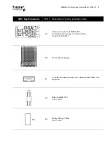
LED / Key/Component
Ref.
Description, Function and Article Code
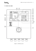
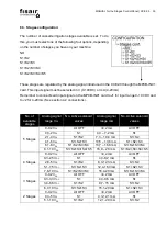
15
Float switch status LED:
Yellow. Indicates level below minimum
Green. Indicates operating level
Red. Indicates maximum water level
Flashing red: Indicates fault
16
Water pump status LED:
Green. Water pump running
Red. Malfunction
17
Display screen
18
Power terminals (X1)
19
Magneto-thermal circuit breaker (U1 in electrical diagram) to
protect water pump
Art. Cod.: 64350010 (55 W single-phase pump)
Art. Cod.: 64350010 (60 W 3-phase pump)
Art. Cod.: 64350005 (90 W single-phase pump)
Art. Cod.: 64350004 (125 W 3-phase pump)
Art. Cod.: 64350005 (240W 3-phase pump)
Art. Cod.: 64350020 (370W single-phase pump)
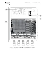
20
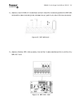
Electronic power card SEF-028.1
Art. Cod.: 523000013
22
Electronic power card SEF-032.1 v2
for steps control.
Art Cod.: 523000017
Summary of Contents for CCE2.0
Page 2: ...MANUAL for the Stages Control Panel CCE2 0 2 ...
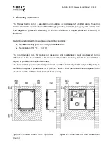
Page 14: ...MANUAL for the Stages Control Panel CCE2 0 14 Figure 3 4 Inside cover CCE2 0 standard ...
Page 53: ...MANUAL for the Stages Control Panel CCE2 0 53 13 Declaration of conformity 13 1 D C Machine ...
Page 54: ...MANUAL for the Stages Control Panel CCE2 0 54 13 2 D C Partly completed machinery ...
Page 55: ...MANUAL for the Stages Control Panel CCE2 0 55 14 Warranty ...
Page 56: ...MANUAL for the Stages Control Panel CCE2 0 56 ...
Page 57: ...IÓN F ...
Page 58: ...IÓN ...
Page 59: ...IÓN MAN P Ev1 Mv1 P P ...
Page 60: ...F IÓN ...
Page 61: ...IÓN ...
Page 62: ...IÓN MAN P Ev1 Mv1 P P ...