


FIREPOWER FP 125,135,165
INSTALLATION 3-8 Manual 0-5123
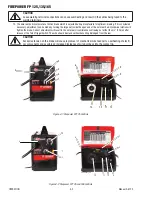
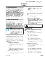
Wire Spool
Inlet Wire Guide
Feedroll
Pressure Adjust Device
Pressure Arm
Gun Cable End
Art # A-09083
Figure 3-8: Wire Feeder Components
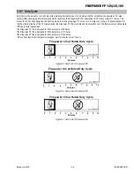
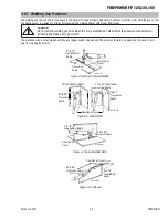
Route the Wire Through the Feedhead
1.
Loosen Pressure Adjust Device (Fig. 3-9).
2.
Open Pressure Adjust Device (Fig. 3-9).
3.
Open Pressure Arm (Fig. 3-9).
4.
Place the end of the wire into the Inlet Wire Guide,
feeding it over the Feedroll. Make certain that the proper groove
is being used (Fig. 3-10).
5.
Pass the wire into the Gun Liner of the Gun Cable End
(Fig. 3-10).
6.
Close the Pressure Arm (Fig. 3-10).
7.
Close the Pressure Adjust Device. Tighten it to a “snug”
condition (Fig. 3-10).
8.
Figure 3-11 shows the result with the wire installed.
NOTE!
If there is too much pressure on the drive
roll the wire gets locked and the motor
could get damaged, If it is too loose the
wire will not feed properly.
Pressure Adjust Device
Pressure Arm
Art # A-09084
Figure 3-9: Opening Pressure Arm
Pressure Adjust Device
Pressure Arm
Spool
Wire Guide
Wire
Feedroll
Gun Cable End
Art # A-09085
Figure 3-10: Inserting Wire
Art # A-09086
Figure 3-11: Wire Installed
Summary of Contents for FP 95 FC
Page 26: ...FIREPOWER FP 125 135 165 INSTALLATION 3 10 Manual 0 5123 This Page Intentionally Blank...
Page 42: ...ESAB FIREPOWER FP 125 135 165 SERVICE 5 4 Manual 0 5123 This Page Intentionally Blank...
Page 49: ...FIREPOWER FP 125 135 165 Manual 0 5123 A 7 APPENDIX This Page Intentiolnally Blank...
Page 51: ......