


FIREPOWER FP 125,135,165
INSTALLATION 3-2 Manual 0-5123
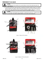
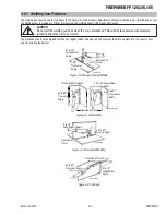
3.06 Installation of Shielding Gas (GMAW) Process
Refer to Figure 3-1.
NOTE!
Shielding Gas is not required if the unit is using self-shielded FCAW (flux cored arc welding) wires.
1. Cylinder Positioning: Chain the cylinder to a wall or other support to prevent the cylinder from falling over. If an optional por-
table mounting arrangement is used, follow the instructions that are provided with it.
2. Remove Cylinder Cap: Remove the large metal cap on top of the cylinder by rotating counter clockwise. Next remove the dust
seal.
3. Cracking: Position yourself so the valve is pointed away from you and quickly open and close the valve for a burst of gas. This
is called “Cracking” and is done to blow out any foreign matter that may be lodged in the fitting.
!
CAUTION
KEEP FACE WELL AWAY FROM THE CYLINDER VALVE DURING “CRACKING”. Never “crack” a fuel gas cylinder
valve near other welding works, sparks or open flames. Ensure that the surrounding area is well ventilated.
4.
Fit Regulator/Flowmeter to Cylinders:
Screw the regulator into the appropriate cylinder. The nuts on the regulator and hose connections are right hand (RH) threaded and
need to be turned in a clockwise direction in order to tighten. Tighten with a wrench.
!
CAUTION
Match regulator to cylinder. NEVER CONNECT a regulator designed for a particular gas or gases to a cylin-
der containing any other gas.
5.
Attach Supplied Gas Line: Attach supplied gas line between the regulator output and the desired input at the rear of the
power supply depending on Spool Gun or MIG Gun use.
Summary of Contents for FP 95 FC
Page 26: ...FIREPOWER FP 125 135 165 INSTALLATION 3 10 Manual 0 5123 This Page Intentionally Blank...
Page 42: ...ESAB FIREPOWER FP 125 135 165 SERVICE 5 4 Manual 0 5123 This Page Intentionally Blank...
Page 49: ...FIREPOWER FP 125 135 165 Manual 0 5123 A 7 APPENDIX This Page Intentiolnally Blank...
Page 51: ......


