FIREPOWER FP 125,135,165
INSTALLATION 3-6 Manual 0-5123
3.08 Polarity Changeover
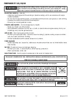
WARNING
ELECTRIC SHOCK CAN KILL! Make certain the machine is unplugged from the power receptacle. Do not
plug machine in until told to do so in these instructions
As delivered from the factory, the output polarity is set to the polarity which matches the welding wire supplied with the unit. The output
terminals are located on the interior panel of the welding power source if you need to change polarity.
PROCESS
POLARITY
CABLE CONNECTIONS
CABLE TO GUN
CABLE TO WORK
1. GMAW – Solid Wire
1. DCEP – Reverse Polarity
1. Connected to (+) Pos.
output terminal
1. Connected to (-) Neg.
output terminal
2. FCAW – Self-shielding Wire – no
Shielding Gas
2. DCEN – Straight Polarity
2. Connected to (-) Neg.
output terminal
2. Connected to (+) Pos.
output terminal
Table 3-1: Process Cable Connections
Connection for GMAW (reverse polarity DCEP)
1. Open the door to the machine.
2. Remove the polarity terminal knobs.
3. Set up the polarity (as per Table 3-1 above) by remov-
ing the leads from the terminals and reversing them if
necessary. Refer to Figure 3-4.
4. Replace the polarity terminal knobs.
NOTE!
Ensure that the polarity terminal knobs
are tightly secured and that there is no
connection between positive and negative
terminals.
Connection for FCAW (straight polarity DCEN)
1. Open the door to the machine.
2. Remove the polarity terminal knobs.
3. Set up the polarity (as per Table 3-1 above) by remov-
ing the leads from the terminals and reversing them if
necessary. Refer to Figure 3-5.
4. Replace the polarity terminal knobs.
NOTE!
Ensure that the polarity terminal knobs
are tightly secured and that there is no
connection between positive and negative
terminals.
Polarity
Terminal
Leads
Polarity
Terminal
Knobs
Gas Hose
Normally
Connected
Art # A-09080
Figure 3-4: Connection for GMAW (reverse polarity DCEP)
Gas Tube
Normally
Disconnected
Polarity
Terminal
Leads
Polarity
Terminal
Knobs
Art # A-09081
Figure 3-5: Connection for FCAW (straight polarity DCEN)
Summary of Contents for FP 95 FC
Page 26: ...FIREPOWER FP 125 135 165 INSTALLATION 3 10 Manual 0 5123 This Page Intentionally Blank...
Page 42: ...ESAB FIREPOWER FP 125 135 165 SERVICE 5 4 Manual 0 5123 This Page Intentionally Blank...
Page 49: ...FIREPOWER FP 125 135 165 Manual 0 5123 A 7 APPENDIX This Page Intentiolnally Blank...
Page 51: ......

