13
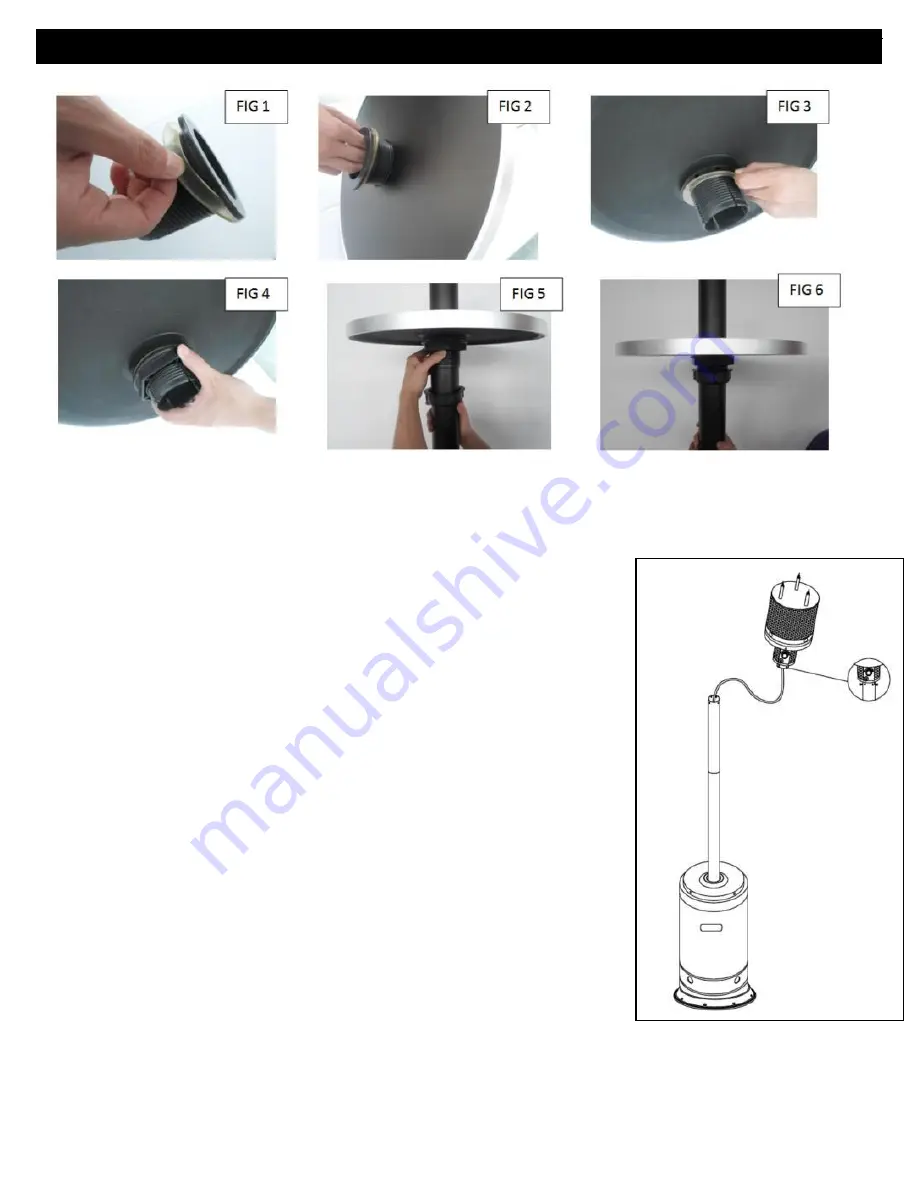
Step 11: Install burner head assembly to the top of the post
Tip: A safe and sturdy ladder will come in handy for the remaining installation steps
Hardware Used:
E: Qt 3) M8x90 Barrel Bolts
a)
Raise the table assembly (if installed in step 10) to approx. 6” below
the top of the post. Then raise the Tank Housing and rest the bottom of
the housing on the post supports to allow access to the tank/cylinder
compartment.
b)
Screw the 3) M8 x 90 Barrel Bolts (E) into the holes located on the
top of the Head Assembly (2) and hand tighten until secure
c)
Remove the 4) M6x10 Bolts and 4) M6 lock Washers that come
preassembled on the bottom of the burner head assembly.
d)
Hold the Head Assembly over the top of the Post and fully route the
Gas Hose (3) down into the Post until it extends into the cylinder
compartment.
e)
Rest the Head Assembly on the top of the Post and
turn the head
assembly
until the controls on the head assembly are lined up directly
above the decal on the post below.
f)
Align the 4 pre-threaded holes on Head Assembly with the 4 holes in
the Upper Post and then re-install the 4) Bolts and 4) Lock washers
which were removed earlier and tighten securely.
ASSEMBLY
Summary of Contents for PH01-S XL Series
Page 3: ...3 SAFETY INFORMATION ...
Page 4: ...4 SAFETY INFORMATION ...


