


26
After the SPN is chosen, the Failure Mode Identifier (FMI) is the next setting. The following FMI’s are available:
High Warning (example: High Temperature Warning)
•
Low Warning (example: Low Temperature Warning)
•
High Shutdown (example: High Temperature Shutdown)
•
Low Shutdown (example: High Temperature Shutdown)
•
Status (example: Fuel tank Leak).
•
Status is used when an event is not essentially high or low but simply exists. An example of this is the Emergency Stop.
3. SCaDa Datalink
When a digital input is configured as SCADA Data Link, the state of the input will be placed into the corresponding MODBUS
register for remote monitoring. The Active State of the input can be selected as HIGH or LOW. The HIGH option should be used for
a normally closed switch and the LOW option should be used for a normally open switch.
5.2 relay and Digital output Programming
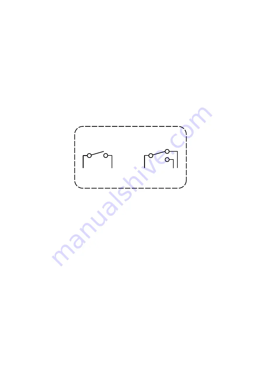
The PowerWizard 1.1 and 1.1+ have six type-A relays. The PowerWizard 2.1 has eight relays. Six of these are type-A relays and the
other two are type-C relays. Type-A is defined as one normally-open contact plus common. Type-C is defined as two contacts,
normally-open and normally-closed plus common.
Relay Outputs
Type A
Type C
figure 21: relay outputs
Each relay is capable of handling 2A @ 30 VDC. The relay contacts are not protected against shorts to battery or ground. Relay
outputs 1 and 2 are typically used for Engine crank and fuel control.
PowerWizard 2.1 has also two current sink outputs, namely digital outputs. PowerWizard 1.1 and 1.1+ have no digital outputs.
Each digital output is capable of sinking 300 mA. The outputs have diagnostics for a short to battery when the driver is on. If a
short to battery persists for five seconds, then the driver will be disabled until the condition is no longer present.
note:
The digital outputs are internally controlled and the active state should always be set to HIGH.
The relay and digital outputs can be configured to the following selections:
Disabled
•
Set to a status or command
•
Set to a system event
•
Set to a SCADA command
•
An output remains in the inactive state when the output is disabled. The control display and the SCADA shows the status
of the output as “Disabled”. An output is active based on the internal logic of the control when the output is set to a status
or a command. An output is active based on the active status of an internal event or the active status of events that are
communicated from other devices across the CAN data link when the output is set to a system event. An active state is sent over
the Modbus when an output is configured for the SCADA data link.


