7
4. A fused disconnect switch or circuit breaker on the incoming power line must be conveniently located near the
brewer, and its location and markings known to the operators.
5. The body of the brewer must be grounded to a suitable building ground.
A ground lug is provided in the brewer next to the power terminal block.
Use only 10 gauge copper wire for grounding.
6. Electrical connections must be secured in-place within the unit to meet
national and local standards.
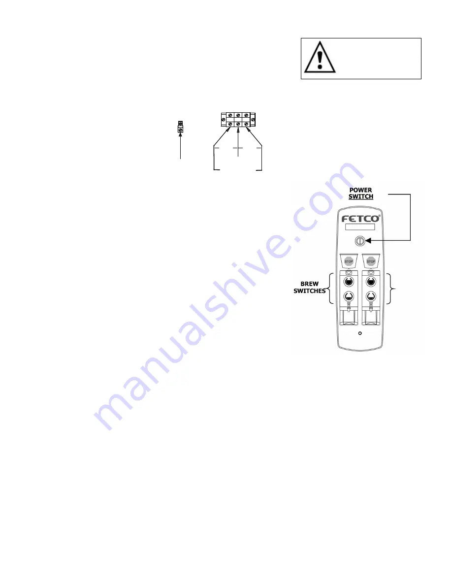
7. Finally, plug the brewer in to the appropriate outlet (120 VAC models), or connect the incoming power wires to
the terminal block as shown in accordance with applicable codes (120/208-240 VAC models only).
L1
L2
N
GROUND LUG
GROUND
WIRE
N
208-240V
120V
120V
Final Setup
1. Turn on the incoming water supply line and inspect both inside and
outside of the brewer for leaks in all fittings and tubes
2. Turn on the incoming power.
3. Press the brewer’s power switch, which is near the top of the control
panel.
4. Within 6 seconds, the hot water tank will begin filling until the water is
sensed by the probe at the top of the tank. The display will read “FIL”.
The heaters will be disabled by the control board until the tank is full.
5. While the water is heating, the display will read “LO” and the actual
water temperature will be displayed. After the water has reached the
set temperature, the display will be blank. There is no “ready” light.
6. Review the Operating Instructions. Brew one full batch (water only) on
each side to confirm proper fill levels. The brewer is factory set with
water only (no coffee) to dispense the correct amount of water. If the
actual volume is slightly different from the programmed volume, fine-
tuning the brewer may be necessary. See #60 – 61 in the Advanced
Settings & Diagnostics section.
7. Re-attach the covers after one final inspection for leaks. Look closely
in the top of the brewer at the dispense fittings during this inspection.
Operator Training
Review the operating procedures with whoever will be using the brewer. Pay particular attention to the following
areas:
1. Always pre-heat the dispensers before the first use of each day by filling them half way with hot water, and
letting them stand for at least 15 minutes.
2. Don't remove the brew basket until it has stopped dripping.
3. Make sure the dispenser is empty before brewing into it.
4. Show how to attach covers, close, and or secure the thermal dispensers for transporting.
5. Show how to remove and clean the Cascading Spray Domes.
6. Show the location and operation of the water shut off valve as well as the circuit breaker for the brewer.
7. Steam from the tank will form condensation in the vent tubes. This condensation will drip into and then out of
the brew baskets. 1/4 cup discharging overnight is possible. Place an appropriate container under each brew
basket when not in use.
8. We recommend leaving the power to the brewer on overnight. The water tank is well insulated and will use very
little electricity to keep the tank hot. Leaving the brewer in the on position will also avoid delays at the
beginning of shifts for the brewer to reach operating temperature.
Warning: To prevent
electrical shock, this
unit must be properly
grounded.
Summary of Contents for CBS-2031ee
Page 4: ...4 Dimensions Utility Connections CBS 2031ee DWG 201141 000 CBS 2032ee DWG 201142 000...
Page 5: ...5 CBS 2041ee DWG 201143 000 CBS 2042ee DWG 201144 000...
Page 14: ...14 Parts Figure 1 CBS 2031ee Main Assembly DWG 101269 B...
Page 17: ...17 Figure 3 CBS 2032ee Main Assembly DWG 101270 B...
Page 20: ...20 Figure 5 CBS 2041ee Main Assembly DWG 101272 B...
Page 23: ...23 Figure 7 CBS 2042ee Main Assembly DWG 101271 B...
Page 28: ......


