Earth terminal
1. Connect the earth terminal on the left-hand pneumatic sub-base with low
impedance (short cable with large cross-sectional area) to the left end plate
of the electrical interlinking module of the product (pre-assembled on deliv-
ery status)
è
2. Ensure that the earth terminal at the left end plate of the electrical interlink-
ing module on the product and the earth terminal at the power supply con-
nection have the same potential and that there are no compensating currents.
8
Commissioning
8.1
Safety
The product is equipped with a pneumatically-piloted shut-off valve. With pre-set
parameters and when the inlet pressure P1 is applied, the valve automatically
switches to the “Pressurisation” state in the following cases:
–
Switch-off of the operating voltage or the load voltage
–
Interruption of the network communication with correspondingly set system
parameters
–
Stopping of the higher-order controller (see manufacturer's specifications),
e. g. in the case of transmission of control programs, parameters, configura-
tion data.
If the valve was previously blocked, the system is pressurised. If the system was
exhausted, pressurisation takes place suddenly.
8.2
Commissioning the product
When connecting the device to a CPX terminal, the system limits must be
observed. The entire system is made up of modules in CPX-Extension series 1 and
modules in CPX-Extension series 2 and can have a maximum number of 5 mod-
ules.
–
Extension series 1: 1 CPX bus node + 3 CPX-EA modules
–
Extension series 2: 1 energy efficiency module MSE6-D2M
Usable CPX modules in CPX-Extension series 1:
–
Max. 4 CPX modules, e. g. 1 CPX bus node and 3 CPX-EA modules
Usable CPX-EA modules in CPX-Extension series 1:
–
Digital CPX-EA modules
–
CPX-4DE, CPX-8DE
–
CPX-4DA, CPX-8DA
–
CPX-8DE/8DA
–
Analogue CPX-EA modules
–
CPX-4AE-U-I
–
CPX-2AA-U-I
–
Max. length of connecting cable: 2 m
The product is delivered with pre-set parameters.
1. Check pneumatic tubing connection.
2. Check earth terminal.
3. Check the electrical wiring.
4. Apply compressed air to the product and switch on the power supply.
Ä
The product is operational with pre-set parameters.
5. Call up the control software.
6. Download the network-specific device description file from Festo's support
portal.
7. Import the device description file into the controller.
8. Activate the network scanner or open the hardware catalogue.
9. Transfer the MSE6-D2M and the bus node form the hardware catalogue into
the software controller (detailed information on the topic can be found in the
documentation on the higher-order controller).
10. Parameterise the MSE6-D2M.
11. Check readiness to operate.
Ä
Upon successful commissioning, the LED module errors
P
and the LED
P2 are dark. The LED P2 illuminates if the pressure at the pneumatic con-
nection p2 is
>
or = 4 (pre-set parameter value).
8.3
Parameterisation
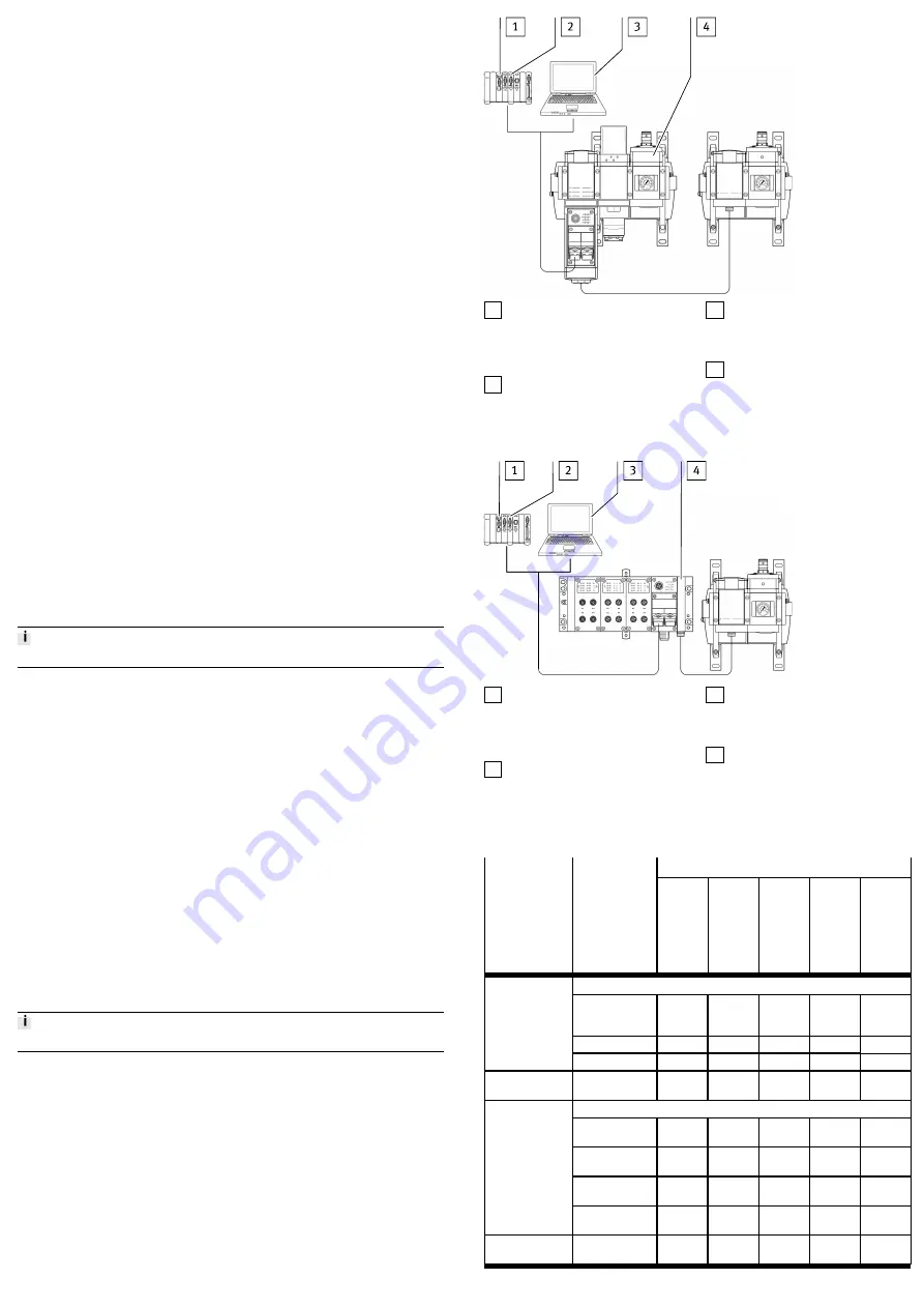
Overview of the module parameters of the function module. A differentiation is
made between changeable module parameters and read-only module paramet-
ers.
Detailed information on parameterisation
è
Overview
The product can only be parameterised via the fieldbus or diagnostic interface of
a CPX field bus node of the control extension series 1 device (MSE6-C2M-…-M or
CPX terminal).
1 Interface module or network scan-
ner/bus master; the desired para-
meterisation can be guaranteed,
e. g. in the start-up phase or after
fieldbus interruptions.
2 User program in the machine con-
troller; parameters can be modi-
fied during operation.
3 Network-specific configurators;
parameters can be modified during
the commissioning phase or dur-
ing troubleshooting.
4 MSE6-C2M-...-M
Fig. 5 Parameterisation via MSE6-C2M-…-M
1 Interface module or network scan-
ner/bus master; the desired para-
meterisation can be guaranteed
e.g. in the start-up phase or after
fieldbus interruptions.
2 User program in the machine con-
troller; parameters can be modi-
fied during operation.
3 Network-specific configurators;
parameters can be modified during
the commissioning phase or dur-
ing troubleshooting.
4 CPX terminal
Fig. 6 Parameterisation via CPX terminal
Module parameters
Function
Function no.
1)
Changeable
module para-
meters
Flow
meas-
ure-
ment
Con-
sump-
tion
meas-
ure-
ment
Pres-
sure
meas-
ure-
ment
Pres-
sure
change
Block-
ing
func-
tion
Monitoring
Bit 2: Under-
voltage in actuat-
or supply
–
–
–
–
n
Bit 6: Limit values
n
–
n
n
–
4828
+ m * 64 + 0
Bit 7: Parameters
n
n
n
n
n
4828
+ m * 64 + 7
Limit value
Start-up
n
–
n
–
–
Units
Bit 0 … 1: Pres-
sure
–
–
n
n
–
Bit 2 … 3:
Flow rate
n
–
–
–
n
Bit 4 … 5:
Consumption
–
n
–
–
–
4828
+ m * 64 + 8
Bit 6 … 7:
Flow standard
n
n
–
–
n
4828
+ m * 64 + 10
Pressure change
sample time
–
–
–
n
–


