


Subject to change – 2018/04
44
è
Internet: www.festo.com/catalogue/...
Terminal CPX-P
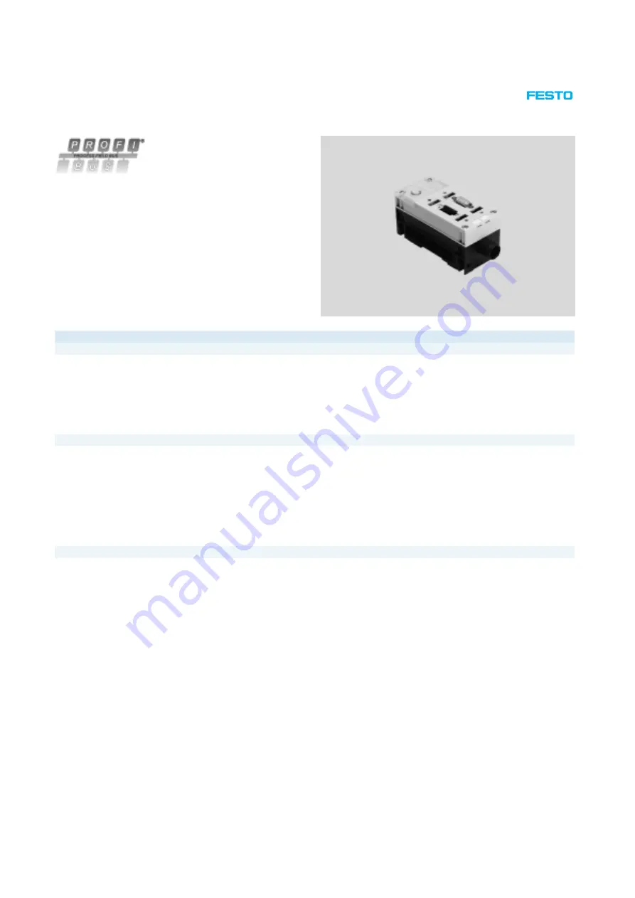
Technical data – Bus node CPX-FB13
Bus node for handling communication
between the electrical CPX-P terminal
and a higher-order master via
PROFIBUS DP.
The bus node is provided with system
supply via the interlinking block and
processes communication with the
I/O modules.
The status of the CPX-P terminal is
displayed as a common message via
four CPX-P-specific LEDs.
The fieldbus communication status is
displayed via the PROFIBUS-specific
error LED.
Application
Bus connection
The bus connection is established via
a 9-pin Sub-D socket with a typical
PROFIBUS allocation (to EN 50170).
The bus connector plug (with
IP65/IP67 protection from Festo or
IP20 protection from other manufac
turers) facilitates the connection of an
incoming and an outgoing bus cable.
An active bus terminal can be connec
ted using the DIL switch integrated in
the plug.
The Sub-D interface is designed for
controlling network components with
a fibre-optic cable connection.
PROFIBUS DP implementation
The CPX-FB13 supports the PROFIBUS
DP protocol to EN 50170 Volume 2 for
cyclic I/O exchange, parameterisation
and diagnostic functions (DPV0).
In addition to DPV0, acyclic commu
nication to the advanced specification
DPV1 is supported. DPV1 provides
acyclic access to advanced system
information and assigns operation
parameters while the controller is
running via the user program.
An example of this is access to the in
tegrated diagnostic memory function,
i.e. storage of the last 40 errors with
timestamp, module, channel and
error type.
With its address capacity of 64 byte
inputs and 64 byte outputs, the
CPX-FB13 supports any configura
tion of I/O modules, including
pneumatic interface.
Points to note in connection with CPX-CEC
When a bus node is combined with a
control block (CPX-CEC, in the fieldbus
remote controller operating mode), the
connected I/Os and/or valves, sensors
and actuators are controlled via the
CPX-P control block.
In this case, the bus node only
provides the communication interface
to the PLC.
Communication between the control
block and CPX-P bus node is
established by interlinking the CPX-P
modules and occupies the following
address capacity in the CPX-P system:
8 byte outputs
8 byte inputs
The remaining address capacity of the
control block or CPX-P system for
actuating the peripherals is:
56 byte inputs
56 byte outputs


