


4
Electrical installation
4.1 Connector pin assignments
The CMMP-AS-…-M3 motor controller is connected to the supply voltage, motor,
external braking resistor and the holding brake in accordance with
è
Hardware
description.
Note
If the polarity of the operating voltage connections is reversed, or if the operat
ing voltage is too high or the operating voltage and motor connections are re
versed, the CMMP-AS-…-M3 motor controller will be damaged.
Overview of connections
[X1]
I/O communication
[X2A]
Resolver
[X2B]
encoder
[X4]
CAN bus
[X6]
Motor
[X9]
Power supply
[X10]
Increment generator input
[X11]
Increment generator output
[X18]
Ethernet interface
[X19]
USB interface
1)
Connection of the PC for commissioning.
è
The cable screening of the motor cable must also be connected to the screening
clamp of the motor controller.
Observe the instructions for safe and EMC-compliant installation
è
Hardware
description.
The main pin allocations can be found as stickers which are included in the scope
of delivery.
5
Commissioning
è
Information for commissioning can be found in the corresponding documenta
tion for the motor controller
è
section 2.2. The following sections provide a con
nection overview and an overview for checking the operating status of the product.
Connecting the motor
1. Insert the plug of the motor cable into the corresponding socket on the motor
and tighten.
2. Insert the PHOENIX plug into the socket [X6] on the device.
3. Clamp the cable shields to the shield terminals (not suitable as strain-relief ).
4. Insert the plug of the encoder cable into the encoder output socket on the mo
tor and tighten.
5. Insert the D-SUB plug into socket [X2A] resolver or [X2B] encoder of the device
and secure the locking screws.
6. Check all plug connectors once again.
Connecting the power supply
1. Make sure that the power supply is switched off.
2. Insert the PHOENIX plug into the socket [X9] on the motor controller.
3. Connect the PE cable of the mains supply to the PE earth socket.
4. Connect the 24 V connections using an appropriate power supply unit.
5. Connect the power supply unit.
6. Check all plug connectors once again.
Connect the PC
1. For commissioning you will need the FCT with CMMP-AS plug-in which can be
found on the CD-ROM supplied with the motor controller or at
è
www.festo.com/sp.
Installation: Launch “Start.exe”; administrator rights are required for installa
tion of the FCT (see Readme.txt).
2. Connect the PC to the motor controller via USB or Ethernet
è
Hardware descrip
tion.
Check readiness for operation
1. Make sure that the controller enable is switched off (controller enable: DIN 5
at [X1]).
2. Switch on the power supplies for all devices. The READY LED on the front of the
device should now light up.
è
If the READY LED lights up red, it indicates a fault. If an “E” appears in the
seven-segment display followed by a sequence of numbers, this is an error mes
sage and you must rectify the cause of the error
è
Hardware description.
If there is no display
1. Switch of the power supply.
2. Wait 5 minutes to allow the intermediate circuit to discharge.
3. Check all connecting cables.
4. Check the functionality of the 24 V power supply.
5. Switch on the supply voltage again.
6. If there is still no display
è
device is defective
6
Service functions and diagnostic messages
6.1 Operation and display components
The CMMP-AS-…-M3 motor controller has three LEDs on the front and a seven-seg
ment display for indicating the various operating states.
Element
Function
Seven segment display
Displays the operating mode and an error code should an error
occur
è
LED1
Lights up green
Ready status
Lights up red
Error
LED2
Lights up green
Controller enable
LED3
Lights up yellow
CAN bus status display
RESET button
Hardware reset
6.2 Seven segment display
The display and the meaning of the symbols shown are illustrated in the following
table:
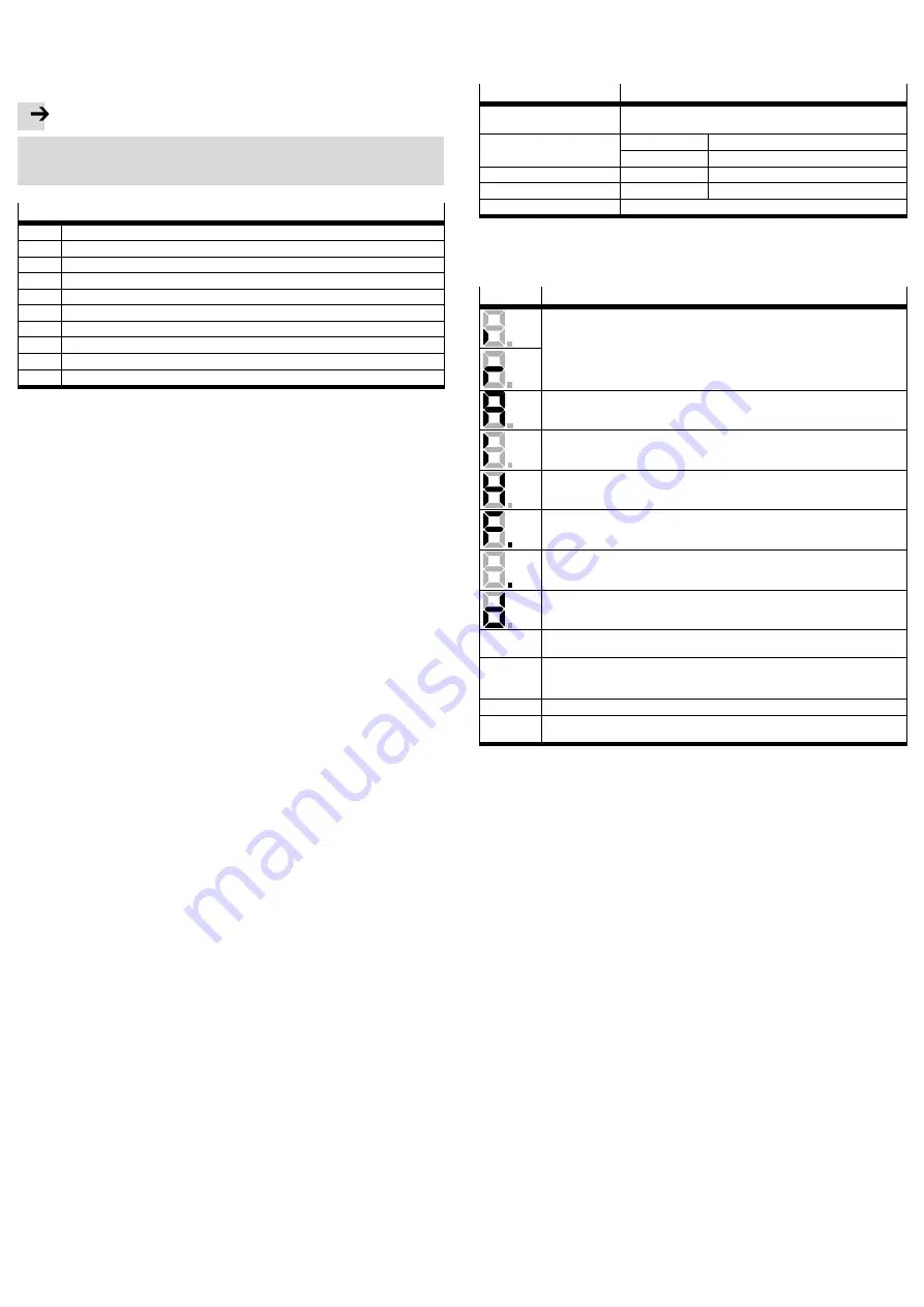
Display
Meaning
The outer segments “rotate” on the display in the speed control operating mode.
The display depends on the current actual position or speed.
The central bar is also active when the controller release is active.
The CMMP-AS-…-M3 motor controller still needs to be parameterised.
(Seven-segment display = “A”)
Controlled torque mode.
(Seven-segment display = “I”)
“H”: (Only applicable when using a safety module) a safety function is initiated
è
safety module description.
“F”: Indicates that firmware is loaded in the flash memory.
“.”: Boot loader active
“d”: Indicates that a parameter set is loaded from the SD card into the controller.
P xxx
Positioning (“xxx” stands for the position number)
The numbers are shown in succession
PH x
Homing: “x” stands for the respective phase of the homing procedure (0: search
phase, 1: creep phase, 2: travel to zero position). The numbers are shown in suc
cession
E xxy
Error message with main index “xx” and subindex “y”
-xxy-
Warning message with main index “xx” and sub-index “y”. Warnings are shown at
least twice on the seven-segment display.
6.3 Diagnostic messages
If an error occurs, the CMMP-AS-…-M3 motor controller displays a diagnostic mes
sage cyclically in the seven-segment display of the motor controller
CMMP-AS-…-M3. The error message consists of an E (for Error), a main index and a
subindex, e.g.: E 0 1 0.
Warnings have the same number as an error message. The difference is that a
warning is displayed with a prefixed and suffixed hyphen, e.g.: .
- 1 7 0 -
.
The meanings and the measures for the message groups are summarised in the
following table. A complete list of all error messages can be found in the
è
Hard
ware description.
7
Repair and disposal
è
Repair of the motor controller is not permissible. If necessary, replace the motor
controller.
è
Observe the local regulations for environmentally-friendly disposal of electronic
modules.


