


SUN P7
14
EN
cod. 3540I811 - 04/2011 (Rev. 00)
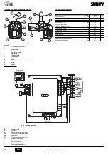
5.2 General view and main components
fig. 13
Key
1
Pressure transducer
2
Controller
3
Burner body
4
Terminal block
5
User interface
6
Heating element
7
Photoresistance
8
Thermostat 85°
9
Burner loading tube
10
Motor
11
Fan
12
Nozzle
13
Grille
5.3 Wiring diagram
fig. 14 - Wiring diagram
Key
FR
Photoresistance
16
Fan
34
Heating temperature sensor
218
Pellet safety thermostat
239
Igniter
297
Air pressure transducer
to
Electrical power supply
B
Auger motor
C
Request contact
D
Shutdown
E
Burner reset
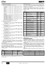
5.4 Technical data table
11
10
6
8
12
9
4
6
7
3
5
2
1
8
9
13
Data
Unit
Value
Max. heating capacity
kW
34.1
(Q)
Min. heating capacity
kW
13.7
(Q)
Max. fuel delivery
kg/h
7.2
Min. fuel delivery
kg/h
2.9
Electrical protection rating
IP
X0D
Power voltage/frequency
V/Hz
230/50
Electrical power input
W
100
Igniter electrical power
W
300
Empty weight
kg
11
Hopper capacity
litres
195
Hopper content
kg
140
Pellet dimensions (max. diameter/length)
mm
6/35
Combustion chamber negative pressure
mbar
-0.2
OUT
+15V
GND
DBM13
L
N
4
5
6
7
8
9
10
11
12
A
B
E
C
D
X2
X1
X3
218
239
16
297
FR
X7
INTERFACCIA
UTENTE BIT01.02
34
L
N
11
10
9
8
7
6
5
4
3
2
1
1
2
3
4
5
6
7
6 5 4 3 2 1
1 2 3 4
3.15 A