background image

SUN P7

11

EN

cod. 3540I811  -  04/2011  (Rev. 00)

3. INSTALLATION

3.1 General Instructions

This unit must only be used for its intended purpose.

This unit can be used with heat generators for solid fuels, compatibly with its characteristics, per-
formance and heating capacity. Any other use is deemed improper and therefore hazardous.
Opening or tampering with the unit's components is not allowed (except for the parts requiring serv-
icing); do not modify the unit to alter its performance or intended use.

If the burner is completed with optionals, kits or accessories, only use original products.

B

BURNER INSTALLATION AND SETTING MUST ONLY BE CARRIED OUT BY QUAL-
IFIED AND SPECIALISED PERSONNEL, IN COMPLIANCE WITH ALL THE INSTRUC-
TIONS GIVEN IN THIS TECHNICAL MANUAL, THE CURRENT PROVISIONS OF
LAW, THE PRESCRIPTIONS OF NATIONAL AND LOCAL STANDARDS, AND THE
RULES OF PROPER WORKMANSHIP.

3.2 Installation in boiler

Place of installation

The room where the boiler and burner are installed must have openings to the outside
as required by the current regulations. If there are several burners or exhausters that can
work together in the same room, the ventilation openings must be sized for simultaneous
operation of all the units.

The place of installation must be free of flammable materials or objects, corrosive gases,
dusts or volatile substances which, drawn by the fan, can obstruct the pipes inside the
burner or the combustion head. The room must be dry and not exposed to rain, snow or
frost.

Fix the burner to the door. Make the electrical connections as shown in cap. 5 (wiring di-
agram). If the burner is installed in a boiler 

SUN P7

, use the special conversion kit. Insert

the temperature probe (contained in the kit) in the sheathing on the cast-iron boiler shell
and make the respective electrical connections.

B

THE BURNER IS DESIGNED TO WORK ON HEAT GENERATORS WITH
COMBUSTION CHAMBER IN NEGATIVE PRESSURE.

THE PELLET HOPPER MUST BE POSITIONED SO THAT THE AUGER/
BURNER FLEXIBLE CONNECTION TUBE IS NOT TWISTED AND/OR BENT.

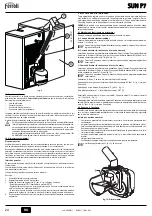
Instructions for installing the pellet burner SUN P7 in the GFG - SFL boiler

Optional kits are available for using the pellet burner with GFG - SFL boilers. For instal-
lation, refer to the instructions contained in the kits.

Install the burner after fitting the kit in the boiler.

Fix the nozzle "

L

" with screws "

M

" and the burner with nut "

N

". Connect the cable "

E

" to

terminals 11 and 12, and the cable "

T

" to sensor "

 V

". Fix the casing "

P

" to the burner

body with screws "

R

" and part "

S

" to the burner.

fig. 4

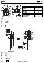
Insert the motor-operated feed pipe 

"Y"

 in the pellet tank "

X

" and carry out the auger-

burner connection so that the flexible tube "

W

" is not twisted and/or bent. Respect the

distance given in the fig. 9.

Adjust the burner as described in the relevant instruction manual and, in particular, set
the parameter u02 on the burner controller as given in the table.

fig. 5

fig. 6

fig. 7

fig. 8

Model

3

4

Nominal heating capacity

kW

24.9

33.4

Nominal heat output

kW

22

30

Parameter

u02

2

5

L
N

4
5
6
7
8
9

10
11
12

3.15 A

L

S

M

M

N

P

R

T

V

E

OK

OK

Summary of Contents for SUN P7

Page 1: ...ISTRUZIONE PER L USO L INSTALLAZIONE E LA MANUTENZIONE EN INSTRUCTIONS FOR USE INSTALLATION AND MAINTENANCE CS N VOD K POU IT INSTALACI A DR B RO INSTRUC IUNI DE UTILIZARE INSTALARE I NTRETINERE RU S...

Page 2: ...o 9 Simbolo Men programmazione 10 Simbolo richiesta accensione bruciatore 11 Non utilizato 12 Simbolo multifunzione in funzione Automatico indica quando l orologio programmatore nella fa scia di richi...

Page 3: ...a e viene salvato Tabella 1 Per uscire dal men premere il pulsante selezione modalit funzionamento M Part 2 fig 1 per 5 secondi Men parametri service L accesso al men parametri avviene premendo il pul...

Page 4: ...l bruciatore o la testa di combustione L ambiente deve essere asciutto e non esposto a pioggia neve o gelo Fissare il bruciatore alla porta Effettuare i collegamenti elettrici come riportato al cap 5...

Page 5: ...icazione in conformit alle norme vi genti Il personale della nostra organizzazione di vendita e del Servizio Tecnico Assistenza Clienti di Zona a vostra disposizione per ogni ulteriore informazione FE...

Page 6: ...atore e sulle pale della girante non vi sia accumulo di polvere riduce la portata d aria e causa conseguentemente combustione inquinante Testa di combustione Verificare che tutte le parti della testa...

Page 7: ...di richiesta D Segnalazione blocco E Sblocco bruciatore 5 4 Tabella dati tecnici 11 10 6 8 12 9 4 6 7 3 5 2 1 8 9 13 Dati Unit Valore Portata Termica max kW 34 1 Q Portata Termica min kW 13 7 Q Porta...

Page 8: ...resente garanzia i guasti e gli eventuali danni causati da trasporto non effettuato a cura dell azienda inosservanza delle istruzioni e delle avvertenze previste dall azienda produttrice e riportate s...

Page 9: ...Burner lighting request symbol 11 Not used 12 Multifunction symbol in Automatic mode it indicates when the programmer clock is in the re quest band if Automatic mode was not selected it indicates Man...

Page 10: ...e data flashes and is stored Table 1 Press the operation mode selection M button detail 2 fig 1 for 5 seconds to exit the menu Service parameters Menu Press the programming button P detail 5 fig 1 for...

Page 11: ...ion head The room must be dry and not exposed to rain snow or frost Fix the burner to the door Make the electrical connections as shown in cap 5 wiring di agram If the burner is installed in a boiler...

Page 12: ...commissioning and maintenance operations must be carried out by Qual ified Personnel in compliance with current regulations The personnel of our sales organ isation and the Local After Sales Technical...

Page 13: ...onents Fan Make sure no dust has accumulated inside the fan and on the blades it reduces the air flow thus causing pollutant combustion Combustion head Make sure all parts of the combustion head are i...

Page 14: ...contact D Shutdown E Burner reset 5 4 Technical data table 11 10 6 8 12 9 4 6 7 3 5 2 1 8 9 13 Data Unit Value Max heating capacity kW 34 1 Q Min heating capacity kW 13 7 Q Max fuel delivery kg h 7 2...

Page 15: ...bol nab dky programov n 10 Symbol po adavku zap len ho ku 11 Nevyu ito 12 Symbol multifunkce v automatick m provozu ukazuje kdy jsou programovac hodiny v p smu po adavku jestli e nebyl zvolen automati...

Page 16: ...provozn ho re imu M 2 fig 1 na 5 vte in Nab dka servisn ch parametr P stup k nab dce parametr se prov d stisknut m tla tka programov n P 5 fig 1 na 10 vte in Zobraz se parametr t01 ozna en n pisem SET...

Page 17: ...ntil torem mohly ucpat vnit n potrub ho ku nebo spalovac hlavici Prostor mus b t such a nesm b t vystaven de ti sn hu nebo mrazu P ipevn te ho k ke dv k m Prove te elektrick p ipojen podle sti cap 5 e...

Page 18: ...born vy kolen pracovn ci s p slu nou kvalifikac v souladu s platn mi normami Dal infor mace v m poskytnou pracovn ci na prodejn organizace a pracovn ci m stn servisn z kaznick podpory FERROLI odm t ja...

Page 19: ...toru a lopatk ch rotoru nen nahromad n prach sni uje pr tok vzduchu a je pak p inou zne isuj c ho spalov n Spalovac hlavice Zkontrolujte plnost v ech st spalovac hlavice zkontrolujte zda nejsou zdefor...

Page 20: ...adavku D Signalizace zablokov n E Odblokov n ho ku 5 4 Tabulka technick ch daj 11 10 6 8 12 9 4 6 7 3 5 2 1 8 9 13 Data Jednotky Hodnota Max tepeln v kon kW 34 1 Q Min tepeln v kon kW 13 7 Q Max pr t...

Page 21: ...ton Override 4 Buton 5 Buton programare 6 Buton 7 Afi aj 8 Simbol func ionare Automat 9 Simbol Meniu programare 10 Simbol cerere aprindere arz tor 11 Neutilizat 12 Simbol multifunc ional n timpul func...

Page 22: ...rametru este suficient s se apese pe tastele i det 4 i 6 fig 1 modificarea va fi salvat automat Dup ce s a modificat parametrul trebuie s a tepta i 3 secunde data clipe te intermitent i este salvat Ta...

Page 23: ...lator pot bloca tuburile interne ale arz torului sau capul de ardere nc perea trebuie s fie uscat i s nu fie expus ploii z pezii sau nghe ului Fixa i arz torul de u Efectua i conexiunile electrice a a...

Page 24: ...INEREA Toate opera iile de reglare punere n func iune i ntre inere trebuie efectuate de Perso nal Calificat i cu calificare recunoscut n conformitate cu normele n vigoare Perso nalul organiza iei noas...

Page 25: ...jul E fig 11 Verific rile pieselor i ale componentelor Ventilatorul Verifica i ca n interiorul ventilatorului i pe palele rotorului s nu existe depuneri de praf acesta reduce debitul de aer i produce...

Page 26: ...act de cerere D Semnalizarea bloc rii E Deblocarea arz torului 5 4 Tabel cu datele tehnice 11 10 6 8 12 9 4 6 7 3 5 2 1 8 9 13 Date Unitate Valoare Putere termic max kW 34 1 Q Putere termic min kW 13...

Page 27: ...9 9 10 10 11 11 12 12 13 14 15 16 17 18 19 2 7 8 14 10 1 2 3 3 10 NO CU 2 4 1 1 1 2 7 1 4 6 1 1 7 1 1 3 7 1 4 e 6 1 00 23 1 1 4 7 1 4 6 1 00 59 1 1 On Off 2 1 1 7 1 ON 7 1 2 On 7 1 ON A 3 Off 7 1 ON A...

Page 28: ...4 ON 4 OFF 11 P 5 1 3 M 2 1 5 u01 SET 01 P 5 1 4 6 1 3 1 M 2 1 5 Service P 5 1 10 t01 SET 01 P 5 1 4 6 1 3 2 P 5 1 10 2 5 B u02 u01 30 80 C 80 C u02 1 5 5 u03 3 1 0 2 0 t01 0 1 0 t02 0 1 1 t03 0 200...

Page 29: ...U cod 3540I811 04 2011 Rev 00 3 3 1 B 3 2 cap 5 SUN P7 B SUN P7 GFG SFL GFG SFL L M N E 11 12 T V P R S 4 Y X W 9 u02 5 6 7 8 3 4 24 9 33 4 22 30 u02 2 5 L N 4 5 6 7 8 9 10 11 12 3 15 A L S M M N P R...

Page 30: ...00 9 3 3 4 230 50 B 3 4 2 4 sez 5 4 40 3 5 1 2 3 P 5 1 5 t 1 SET 01 1 5 0 0 1 4 4 FERROLI 4 1 3 1 3 A 7 8 14 A B ON On 7 8 14 A C ON On 7 8 14 A A B C M 2 1 5 2 P 5 1 3 SET 03 00 A 01 B 02 C 4 6 1 3...

Page 31: ...3 4 1 30 2 3 4 O2 5 9 CO 150 1000 service 2 cap 2 4 CO T18 5 6 5 u02 1 service 1 cap 2 4 6 u02 4 3 A 10 B B A A B C D E 11 4 4 7 1 A P 5 1 1 F 3 5 5 1 12 A C D E B A01 F02 A02 A04 03 51 04 12 10Pa F05...

Page 32: ...9 297 A B C D E 5 4 11 10 6 8 12 9 4 6 7 3 5 2 1 8 9 13 34 1 Q 13 7 Q 7 2 2 9 IP X0D 230 50 100 300 11 195 140 6 35 0 2 OUT 15V GND DBM13 L N 4 5 6 7 8 9 10 11 12 A B E C D X2 X1 X3 218 239 16 297 FR...

Page 33: ...Symbol po iadavky na zapnutie spa ova a 11 Nepou it 12 Symbol multifunkcie pri Automatickej prev dzke indikuje kedy s hodiny program tora v re ime po iadavky na innos ak nebola zvolen Automatick prev...

Page 34: ...y stla te tla idlo vo ba re imu innosti M Ozn 2 fig 1 na 5 sek nd Ponuka parametrov slu ieb Pr stup k ponuke parametrov sa dosiahne stla en m tla idla programovania P ozn 5 fig 1 na 10 sek nd Zobraz s...

Page 35: ...terne ale arz torului sau capul de ardere nc perea trebuie s fie uscat i s nu fie expus ploii z pezii sau nghe ului Fixa i arz torul de u Efectua i conexiunile electrice a a cum se arat n cap 5 schema...

Page 36: ...enie do innosti a dr bu musia vykona kvalifikovan a vy kolen pracovn ci v s lade s platn mi normami Pracovn ci na ej organiz cie a pre v dzok servisn ch stred sk v m radi poskytn podrobnej ie inform c...

Page 37: ...a a na lopatk ch rotora nie je nahromaden prach tento zni uje prietok vzduchu m sa n sledne zni uje kvalita spa ovania a zvy uje mno stvo kodliv n v spalin ch Spa ovacia hlavica Skontrolujte i s v etk...

Page 38: ...Signaliz cia zablokovania E Zablokovanie spa ova a 5 4 Tabu ka s technick mi dajmi 11 10 6 8 12 9 4 6 7 3 5 2 1 8 9 13 daje Jednotka Hodnota Max tepeln v kon kW 34 1 Q Minim lny tepeln v kon kW 13 7 Q...

Page 39: ...ies with the following EU directives Low Voltage Directive 73 23 amended by 93 68 Electromagnetic Compatibility Directive 89 336 amended by 93 68 President and Legal Representative Cav del Lavoro Dant...

Page 40: ...FERROLI S p A Via Ritonda 78 a 37047 San Bonifacio Verona ITALY www ferroli it...

Reviews: