


SUN P7
12
EN
cod. 3540I811 - 04/2011 (Rev. 00)
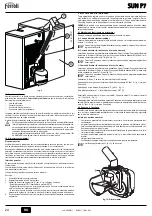
fig. 9
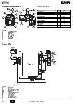
3.3 Electrical connections
The burner is equipped with a multipole terminal block for the electrical connections; re-
fer to the wiring diagram in section "
4 Technical Characteristics and Data
" for the con-
nections. The connections to be made by the installer are:
•
Supply line
•
Request contact
•
Auger motor connection
•
Temperature probe connection
The length of the connection cables must allow the burner and, if necessary, the boiler
door to be opened. If the burner power cable is damaged, it must only be replaced by
qualified personnel.
The burner must be connected to a single-phase 230 Volt-50Hz electric line.
B
Have the efficiency and suitability of the earthing system checked by profes-
sionally qualified personnel; the Manufacturer declines any liability for damage
caused by failure to earth the system. Also make sure the electrical system is
adequate for the maximum power absorbed by the unit, as specified on the boil-
er dataplate.
Make sure to respect the polarities (LINE: brown wire / NEUTRAL: blue wire /
EARTH: yellow/green wire) when making connections to the electric line.
3.4 Fuel supply
General Instructions
The burner must be fed with the type of fuel for which it is arranged, as specified on the
dataplate and in the technical data table insec. 5.4 of this manual.
The user is advised to use good quality pellets, since low quality pellets result in low heat
outputs, high ash content with subsequent need of frequent cleaning, possible early wear
of burner parts exposed to the fire, clogging of the auger and burner due to excess loose
sawdust, and operation shutdowns due to sedimentation of unburnt materials inside the
burner.
Pellet loading
Pellet loading can be activated within 40 minutes of switching on the power to the burner.
Within this time, the system makes available three 5-minute attempts, during which only
the auger is activated.
The burner cannot be lit during pellet loading.
Sequence:
1.
Switch on the power to the burner.
2.
Wait for the pre-ventilation stage to end.
3.
Press the programming button “P” (detail 5 - fig. 1) for 5 seconds.
- The parameter “tØ1” is displayed: identified by the message SET 01.
- Set the parameter to 1 to start the first 5-minute attempt. It can be stopped at any
time by setting the parameter 0.
- If the first attempt was insufficient, repeat the previous sequence, setting the pa-
rameter to 0 and then to 1: for the second and third loading attempt.
4.
To carry out another 3 attempts, switch power to the unit off and then on again.
4. SERVICE AND MAINTENANCE
All adjustment, commissioning and maintenance operations must be carried out by Qual-
ified Personnel in compliance with current regulations. The personnel of our sales organ-
isation and the Local After-Sales Technical Service are at your disposal for any further
information.
FERROLI
declines any liability for damage and/or injury caused by unqualified and un-
authorised persons tampering with the unit.
4.1 Burner operation methods
Three methods are envisaged for managing burner lighting:
A - Burner management (default setting)
The request for burner lighting is activated only on closing of the contact on terminals 7-
8 (see fig. 14).
A
The clock and the set weekly programme are bypassed: the exact time does
not have to be set.
B - Burner management (with internal Clock or Contact)
The request for burner lighting can be activated by the Clock (during Automatic Heating
Mode in ON Band or in Manual On Heating Mode) or with closing of the contact on ter-
minals 7-8 (see fig. 14).
A
It is necessary to set the Clock and possibly modify the weekly programme de-
fault setting.
C - Burner management (with internal Clock and Contact)
The request for burner lighting is activated by the Clock (during Automatic Heating Mode
in ON Band or with Manual On Heating Mode) and if the contact on terminals 7-8 is
closed (see fig. 14).
A
It is necessary to set the Clock and possibly modify the weekly programme de-
fault setting.
The selection of A, B or C occurs from the Clock user menu.
Press the operation mode selection button "M" (detail 2 - fig. 1) for 5 seconds.
Press the Programming button "P" (detail 5 - fig. 1) twice.
Parameter no. 3, identified by the message SET 03, is displayed.
Set to 00 for mode A, 01 for mode B, or 02 for mode C with the + and - buttons (details
4 and 6 - fig. 1).
After selecting the method, it is necessary to wait 3 seconds: the data flashes and is
stored. Press the operation mode selection "M" button (detail 2 - fig. 1) for 5 seconds to
exit the menu.
4.2 Start-up
Checks to be made at first lighting, and after all maintenance operations involving dis-
connection from the systems or an intervention on safety devices or parts of the burner:
Before lighting the burner
•
Make sure the burner is correctly fixed in the boiler with the preliminary settings in-
dicated above.
•
Make sure the boiler and system are filled with water or diathermic oil, the water cir-
cuit valves are open and that the flue pipe is free and correctly sized.
•
Check closing of the boiler door, so that the flame is only generated inside the com-
bustion chamber.
•
Check the correct positioning of the auger and the burner connection flexible tube.
•
Fill the hopper with pellets.
•
Check the correct positioning and connection of the temperature probe.
A
Make sure the grille (detail 1 fig. 10) is clean.
fig. 10 - Burner grille
Y
W
X
min. 600
1


