background image

FALCON  II

24

6. MAINTENANCE AND CLEANING 

The following operations must be carried out by Corgi registered engineers only. 

6.01 Annual Servicing

The following should be checked at least once a year:
• Water pressure in the central heating system when cold should be about 1 bar. If this is not the case, 

bring it back to this value.

•  Check control and safety devices (gas valve, flow meter, thermostats, etc) are functioning correctly.
• The burner and heat exchanger must be clean. To avoid damage, always clean them with a soft brush or 

compressed air. Never use chemical products.

•  The expansion vessel must be checked (precharge 1 bar).
•  Check there are no leaks in the gas and water circuits.
•  Check the air-flue gas duct terminal is free from obstructions and sound.
•  The electrodes must be free from corrosion build up and correctly positioned.
•  Gas flow and pressure must correspond to the values given in the Technical Data (page 5).
•  The pump must be free to rotate.

6.02 Cleaning the boiler and burner

The boiler should be serviced annually.  The heat exchanger and burner must never be cleaned with chemical 
products or steel brushes. Particular attention must be paid to all seals and fixings associated with the 
room-sealed compartment (gaskets, grommets, etc). Air leakage would cause pressure inside the compartment 
to drop, possibly tripping the differential pressure switch and thus shutting down the boiler. After cleaning 
particular attention should also be paid to checking stages of start-up and operation of the thermostats, 
gas valve and pump. 

6.03 Servicing procedure

1.   Visually check boiler for correct intallation and flueing.
2.  Isolate electricity check fuse is 3amp.
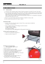
3.  Remove case by undoing the two screws locate at the bottom rear corners, lift slightly and pull forward.
4.  Carry out preliminary electrical checks at boiler junction box. This is located in the centre of the boiler 

at the bottom and can be accessed be the removal of a single screw. Any faults found must be rectified 
before proceeding.

5.  If electrical checks prove O.K. replace cover and secure with screw.
6.  Attach a manometer to the boiler gas inlet test point, turn on electricty and fire boiler for hot water, check 

inlet pressure. This should be 20mbar 

minimum

 for NG and 37mbar for LPG. If this is not the case there is a 

supply problem and this will need to be remedied.

7.  If inlet pressure is O.K. shut down boiler and remove manometer from gas inlet pressure test point and attach 

it to the boiler burner pressure test point. Reseal inlet pressure test point.

8.  Fire boiler for hot water and check that the maximum pressure is 13.0mbar for NG and 35.5mbar for LPG. 

Turn off tap. Turn P3 on the main circuit board to minimum and fixe the boiler for heating, check that the 
burner pressure reads 2.5 mbar for NG and 7.0mbar for LPG. Turn P3 back to max position. Shut down boiler, 
remove manometer, seal test point and re-attach modureg lead. If the pressures are not as specified they will 
need to be adjusted on the gas valve(see page 22 - installation manual).

 10. Remove fan by undoing the two fan securing screws tilt the front of the fan upwards to detach it from the 

securing pin and withdraw it from the boiler, disconnect the wires and air pressure switch tubes.

11.  Take off the combustion chamber cover by removing the three securing screws.
12.  Lift off flue hood and flue baffle plate. 
13.  Pull off the ignition and flame rectification leads from their respective electrodes.
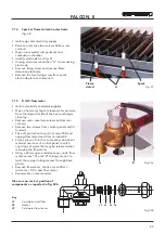
14.  Undo the gas union in the centre of burner rail and take out the two securing screws. Remove the burner 

rail and clean rail and injectors.

15.  Remove two screws securing the burner assembly and remove the assembly. Clean burners.

Summary of Contents for Falcon II

Page 1: ...INSTALLATION SERVICING AND USER INSTRUCTIONS G C NO 47 267 24 Copper Wall Mounted Combination Gas Fired Boiler for Central Heating and Domestic Hot Water Production Fan Assisted Room Sealed Compartme...

Page 2: ...he last pages of this manual This record must be completed and left with the end user All CORGI Registered Installers carry a CORGI ID card and have a registration number Both should be recorded in yo...

Page 3: ...heating circuit set to open at 3 bar Built in Expansion vessel Variable speed pump Central heating flow temperature adjustment thermostat Domestic hot water flow temperature adjustment thermostat Cen...

Page 4: ...to function with natural gas or liquid Petrolium Gas converted appliances Key 1 3 4 central heating flow outlet 2 1 2 domestic hot water flow outlet 733 460 430 85 14 362 200 720 60 115 100 75 189 Di...

Page 5: ...c hot water production gas pressures to the burner must correspond to the maximum output given in table for the type of gas Gas pressure must be adjusted during maximum draw off of domestic hot water...

Page 6: ...P O I P IN OUT MIN GRUNDFOS FERROLI 114 34 20 21 90 50 16 28 32 26 19 49 132 5 56 27 91 62 10 8 7 84 85 44 136 14 42 9 11 36 98 63 157 145 0 5 1 2 3 4 6 OUT I MIN AIR IN AIR IN FLUE OUT C H OUT D H W...

Page 7: ...output to the central heating water simply adjust the main burner via the electronic control board fig 4 and 5 and see paragraph 5 04 page 23 The diagrams indicate the variation in heat output to the...

Page 8: ...NITIAL SYSTEM PRESSURE bar TOTAL WATER CONTENT of SYSTEM 3 0 0 5 1 0 1 5 1 0 1 5 2 0 1 5 2 0 2 0 EXPANSION VESSEL VOLUME litres LITRES 25 3 5 6 5 13 7 4 7 10 3 8 3 50 7 0 12 9 27 5 9 5 20 6 16 5 75 10...

Page 9: ...e boiler is installed does not require a purpose provided vent when using the standard concentric flue Flue System The boiler allows the flue outlet to be taken from the rear of the boiler from either...

Page 10: ...ection between the boiler s central heating system and the mains water supply The use of mains water to charge and pressurise the system directly is conditional upon the Local Water Byelaws Again any...

Page 11: ...100 H From a surface facing the terminal 600 I Facing another terminal 1 200 J From opening door window in carport into dwelling 1 200 K Vertically from a terminal on the same wall 300 L Horizontally...

Page 12: ...wall bracket to the wall using an antitheft nut on the right side and a standard nut M8 on the left side Mount the boiler on the wall bracket and fix using an antitheft nut on the left side and a sta...

Page 13: ...rrectly positioned see fig 13 N B the diameter of the hole is stamped on the restrictor Boiler is fitted with 47 restrictor as standard Holes 47 50 52 Fig 13 Choice of restrictor With concentric pipes...

Page 14: ...Vertical concentric connection 1KWMA31Y D S L 125 70 50 30 95 80 80 3 mm m 60 80 70 min between 10 e 60 mm 190 270 Fig 15 A vertical connector can be supplied for vertical discharge with concentric pi...

Page 15: ...gas duct must be sealed with the gasket where they join the boiler fig 16 Outside the pipes should protrude from the wall between 10 and 60 mm fig 16 Between 10 60mm 3 03 3 Maximum concentric flue le...

Page 16: ...ustible insulating material to prevent condensation The flue pipe should be supported at intervals of not more than 1 8m and the support should be preferably below a joint 3 04 2 Two pipe flue system...

Page 17: ...erminal 80 mm Outlet flue air inlet for concentric system 100 60 mm Pipe fitting for outlet flue 80 mm Outlet flue air inlet for connection with split end 80 mm 1 1 1 2 1 2 2 2 1 5 2 5 REDUCTION 5 2 4...

Page 18: ...7 6 3 2 5 1 13 m 13 m Fig 19 Example of wall inlet outlet 2 pipe application Example of roof inlet outlet Example of direct roof flue outlet and wall air inlet 3 04 3 Example of other installation wit...

Page 19: ...op to bring it back to the original value During operation water pressure in the boiler when hot should be about 1 5 2 bars After filling always close and disconnect the filling loop Note If there is...

Page 20: ...air pressure switch fig 2 part 43 The differential air pressure switch is a safety device which allows the main burner to ignite only after having verified that the fan is working correctly If the di...

Page 21: ...eting the start up procedure correctly the burners fail to ignite and the boiler shut down warning lights up wait about 15 seconds then rotate the knob 98 fig 2 against spring pressure to the RESET po...

Page 22: ...adjust minimum pressure by potentiometer P5 Adjust potentiometre P3 at maximum clockwise Adjust max pressure by rotating screw E clockwise to increase pressure and anticlockwise to reduce pressure Re...

Page 23: ...g the central heating flow t by varying pump flow head The thermal head t the difference in temperature between the delivery water and return water in the central heating circuit must be less than 20...

Page 24: ...ers lift slightly and pull forward 4 Carry out preliminary electrical checks at boiler junction box This is located in the centre of the boiler at the bottom and can be accessed be the removal of a si...

Page 25: ...rature before this test is carried out normally 10 15 minutes CO CO2 ratio should not exceed 0 0080 Immediately after servicing 0 0040 at any other time 30 Refit case and secure with screws 31 Leave b...

Page 26: ...e Re open cocks and re charge the system to about 1 bar and vent boiler and radiators Re charge to 1 bar if necessary Upon completion of the work the following Should be checked I Gas soundness of all...

Page 27: ...Water pressure switch D H W sensor Safety valve A B C D D C A F E 7 07 D H W temperature sensor or Central Heating Temperature Sensor fig 28 Isolate electricity and water supplies Remove outer case tw...

Page 28: ...city supplies Remove outer case two screws bottom rear corners Remove room sealed cover Disconnect fan electrical leads A and note positions Disconnect air pressure tubes from air pressure switch B no...

Page 29: ...move outer case two screws bottom rear corners Remove two screws from control panel and tilt forward Take off protective cover from main PCB and unplug flow meter lead from terminal X6 Place a piece o...

Page 30: ...p body by removing the U clip from the left hand side Disconnect the boiler return pipe and disengage the pump lower connection by removing the U clip C Disconnect the pump to heat exchanger connectio...

Page 31: ...e boiler thermostat is set to maximum than the burner pressure will go to maximum effectively bypassing the auto range rating facility Domestic Hot Water Mode External Call for D H W Flow meter regist...

Page 32: ...the flow meter has not operated Boiler will not light for C H If the boiler works for D H W but not for heating the fault is most likely to be external controls i e clocks or room thermostats Integra...

Page 33: ...C H output and maximum D H W temperature both are adjustable by the controls on the facia and because the boiler features automatic range rating no adjustments need to be made Electro mechanical relay...

Page 34: ...k water pressure switch wiring connection NO Does fan run at full speed NO Go to CHART 2 NO YES Does CH Pump run If the boiler temperature is less than 5 C frost protection is activated Disconnect CH...

Page 35: ...ain board Check and if necessary replace limit thermostat Go to chart 4 Chart 3 Check Central Heating operation Wait 2 minutes DHW taps closed Put CH temperature selector to maximum Ensure external co...

Page 36: ...itch YES Differential air pressure across the air pressure switch is greater than 180 Pascal Go to chart 5 YES NO Check and clean fan Check flue and air intake are correct and clean Check Venturi and...

Page 37: ...ck electrodes and leads for damage and correct connection Check and if necessary replace P C B Adjust with P4 ignition burner pressure Check and if necessary clean burner Check and if necessary clean...

Page 38: ...ure adjustment P3 Central heating flow output adjustment P4 Ignition gas pressure adjustment P5 Minimum adjustment pressure 9 ELECTRICAL AND FUNCTIONAL SCHEME 9 01 Main components layout on electronic...

Page 39: ...TS CONNECTING 230 V TO THE ROOM THERMOSTAT TERMINALS WILL IRREPARABLY DAMAGE THE ELECTRONIC BOARD 81 Ignition electrode 82 Sensor electrode 98 Off On Reset switch 114 Low water pressure switch 136 Flo...

Page 40: ...rease and anti clockwise to decrease the water temperature Heating and Hot Water WINTER To obtain heating from the boiler turn the temperature regulator B clockwise to the maximum position ensure that...

Page 41: ...Failure to observe these requirements may lead to prosecution Electrical Supply WARNING This appliance must be earthed The electrical wiring must be carried out by a competent electrician The colours...

Page 42: ...ON time eg 12 30 Display 4 1 Use button and to set 2nd OFF time eg 14 00 Display 5 1 Use button and to set 3rd ON time eg 16 00 Display 6 1 Use button and to set 3rd OFF time eg 23 30 Display 8 On com...

Page 43: ...FALCON II 43...

Page 44: ...R THE DOMESTIC HOT WATER MODE MEASURE RECORD GAS RATE ft3 hr MAXIMUM BURNER OPERATING PRESSURE IF APPLICABLE mbar COLD WATER INLET TEMPERATURE C HOT WATER OUTLET TEMPERATURE C WATER FLOW RATE lts min...

Page 45: ...TS SIGNATURE SERVICE 3 DATE ENGINEER NAME COMPANY NAME TEL No CORGI ID CARD SERIAL No COMMENTS SIGNATURE SERVICE 4 DATE ENGINEER NAME COMPANY NAME TEL No CORGI ID CARD SERIAL No COMMENTS SIGNATURE SER...

Page 46: ......

Page 47: ......

Page 48: ..._________________ Service Engineer ________________ BECAUSE OF OUR CONSTANT ENDEAVOUR FOR IMPROVEMENT DETAILS MAY VARY SLIGHTLY FROM THOSE QUOTED IN THESE INSTRUCTIONS Please note to avoid incurring u...

Reviews: