7
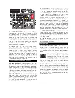
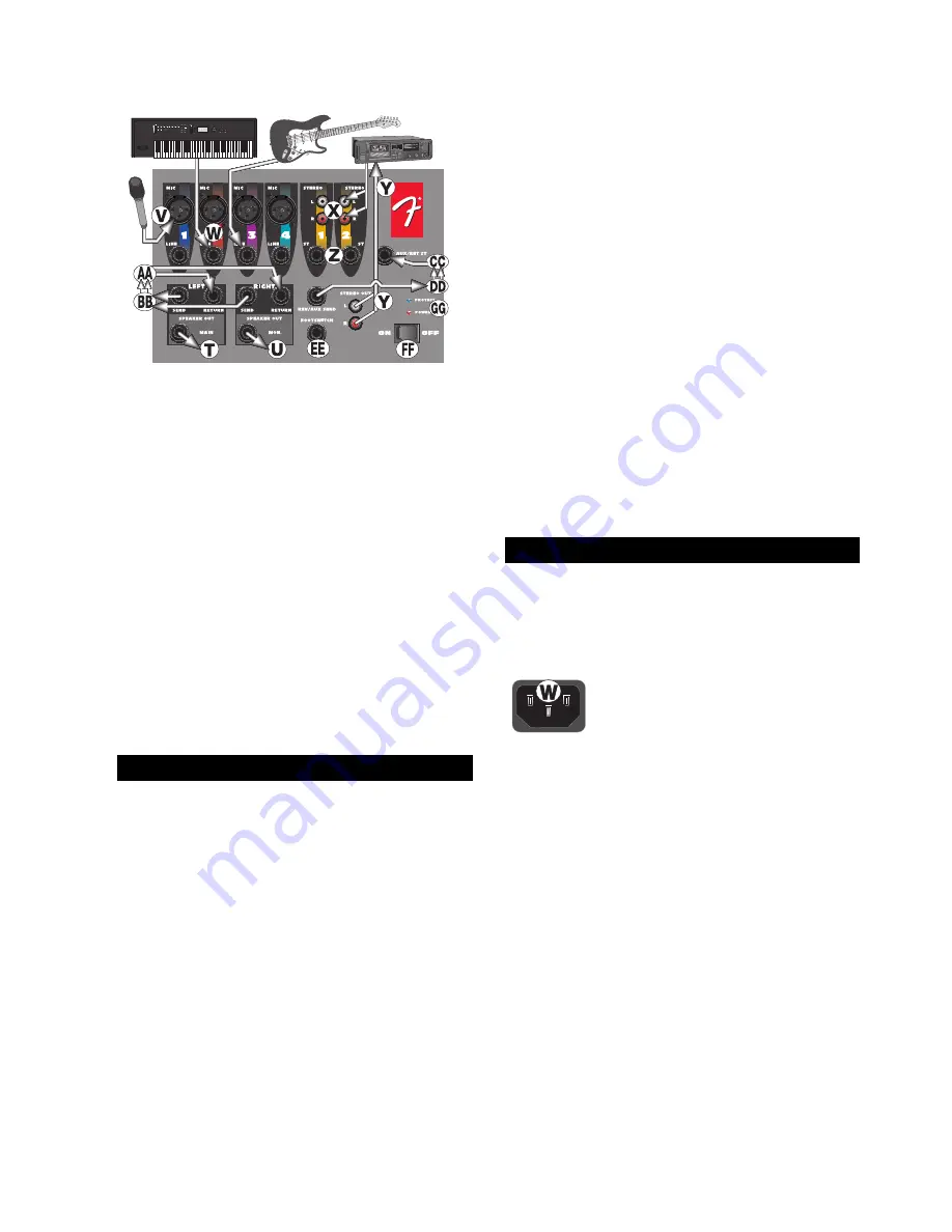
X & Z. STEREO INPUTS
– Stereo phono (RCA) input
jacks and 1/4” TRS jacks (wired for Tip=Left, Ring=Right
and Sleeve=Ground, the standard format of commercially
available cables) designed for use with a tape player, CD
player, or any other stereo source. Use these jacks for
connecting the output of a computer sound card or other
similar device to your Passport. Adapters that convert an
1/8” male plug to RCA male phono plugs are readily
available at electronics stores. Note: These connectors
are set at a constant “line level”.
Y. STEREO OUT
– The Tape Out RCA jacks provide a
mix output that is independent of the Master Level
Controls. Connect these to the inputs of a recording
device, such as a cassette or DAT recorder, to record
your event. Changes made during the performance, to the
input level controls, channel EQ, and reverb controls will
be heard in the Tape Out mix. Changes made to the
master level controls will not effect the level of the
recording. Adjust recording levels according to the
instructions on your recording device.
DD. REV/ AUX SEND
– Plug your external effects signal
processor in here. Although the Passport is already
equipped with on-board digital reverb, an external effects
signal processor can be incorporated into the Passport’s
signal flow. This 1/4 inch output jack is designed to feed
the Passport’s effects bus signal to an external signal
processing device, such as a digital delay or a chorus.
CC. AUX RETURN
– Plug your external effects signal
processor’s output signal in here. This 1/4 inch input
stereo jack is designed to accept signals from an external
processing device, such as a digital delay or a chorus unit.
This input can also be used as a stereo input with the
volume controlled at the master volume knobs.
EE. FOOT SWITCH
– The Footswitch connector allows
the internal reverb return to be muted, or shut off, through
the use of a simple foot operated switch (Fender part
number 099-4052-000). The footswitch should be wired
to connect the tip to the sleeve to turn the reverb off, and
requires a standard speaker or instrument cable.
AA & BB. – AMPLIFIER SEND/ RETURN JACKS
– Each
channel of the amplifier has a Send and Return jack.
These jacks provide a point to patch in an equalizer, or
other processor into the sound system. The signal at the
send jack is located after the mixer section and before the
power amplifier. The send jack should be connected to
the input of the external device. The return jack is a patch
point that enters into the power amplifiers. The return jack
should be connected to the output of the external device.
T & U. SPEAKER OUTPUTS
– These are speaker level
(powered) output jacks designed to feed each of your
Passport speaker enclosures. Use the enclosed cables (or
other speaker cable) to connect the Passport’s speakers
to the power tower.
FF. POWER SWITCH
– Turns the AC power ON and
OFF. When the switch is in the OFF position, your Pass-
port is completely shut down.
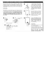
AC CONNECTOR/ LINE CORD
– The Passport is
equipped with a grounding type IEC supply cord to
reduce the possibility of shock hazard. Be sure to connect
it to a grounded AC receptacle.
DO NOT ALTER THE AC
PLUG.
The power mains (AC) fuse and fuse holder
are under the IEC (power cord) socket.
Replacement fuses must be of the same
rating (6.3A, 250V) and size as originally
equipped. To replace a blown fuse, re-
move the IEC power cord. Pull out the fuse holder and
find the spare fuse inside.
Your Passport system is capable of running on battery
power. The off-white plastic connector on the rear of your
Passport is the DC power input connector for connecting
the Passport DC-DC converter. The converter is then
connected to a battery. Available accessories include the
Passport DC-DC converter (Fender part number
069-1002-000) and 12 volt battery pack (Fender part
number 069-9003-000).
AUX AND FOOTSWITCH JACKS
REAR PANEL
Summary of Contents for Passport PD-250
Page 8: ......


