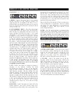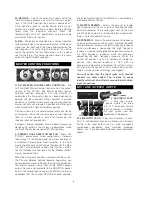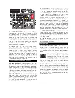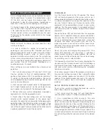
Belt Pack Transmitter Unit (Executive System)
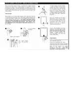
The Belt Pack transmitter has a 4-pin input connector for use with the interchangeable microphones and instrument cable. The microphone and
instrument cables have a miniature jack plug. These have threaded collars to assure secure attachment to the transmitter. When attaching an input
source, make sure to insert its jack plug, then turn clockwise to lock into place
Located on the front panel is an on/off switch and battery low indicator. The Power LED will flash briefly upon turn-on when the battery is in good
condition. When the LED is on continuously, the battery level is too low for normal operation.
On the side of the transmitter are level controls. A level switch provides two input level settings – GT (electric guitar) and MT (microphone). When
in the MT position, the Gain control adjusts the input gain for the microphone. The gain is fixed (and the gain control is inoperative) when in the GT
position.
The transmitter uses one 9-volt alkaline battery, with the battery compartment accessed on the lower right side. Take care to place the battery into its
housing in the correct direction. Look carefully at the battery and identify the plus or positive terminal.
Lavalier Microphone
For general purpose public speaking a lavalier microphone, sometimes known as a lapel microphone, can be very effective. One advantage of this type
of microphone is its relative invisibility. The microphone element is an electret-condenser type.
Headset Microphone
This microphone is essentially of the same type as the lavalier microphone. Fender’s design features a number of advantages for entertainment and
presentation applications. The Fender headset system can be worn securely and comfortably even when used by physically active performers or
instructors. It is designed to go underneath and around the hairline at the back of the neck and fix lightly but securely to the ears of the user.
The headset assembly has a number of adjustments. The neckband is adjustable for size and fit. The pivot arm tension and length can be adjusted. Do
not adjust the arm without loosening the screws slightly.
Instrument Cable
The instrument cable allows virtually noise-free, high quality wireless transmission of instruments or line level sources. The cable simply plugs
directly into the source instrument and the transmitter.
Receiver
Custom Docking Receiver
The wireless receiver is built into the “docking” unit that mounts inside Passport’s storage compartment. All power, audio and antenna connections
are built into the docking receiver.
When you install the docking receiver, audio connections are automatically made to input channel one of the Passport. In other words, input channel
one is now dedicated to the Wireless System. The Wireless Systems come with “blanking plugs” (install in the XLR and ¼” jacks for channel one)
intended as a reminder that this input is in use.
Docking Receiver Indicators
The Passport docking receiver receives power from the Passport. When the Passport main power switch is on (*), the red “Power” LED on the
Wireless docking receiver will illuminate.
* For DC operation only: The Passport front panel ON/OFF switch is not operational when used with a DC-DC converter. The Passport is turned on
and off via the DC Converter On/Off switch. The Wireless Module power LED (red) will illuminate as normal.
The “Signal Present” Green LED on the docking receiver will illuminate when the transmitter is turned “on”- showing the receiver is “seeing” a signal
from your transmitter.
Tone Key
With the Passport Wireless System, the transmitter and receiver are locked to a specific tone key frequency that is carried “invisibly” with the signal
from the transmitter. If the receiver loses this tone key, it soft-mutes the output of the receiver. In this way, should for example, the battery run low
in your transmitter, and its transmission is interrupted, no annoying noises or spurious signals will be fed to the system.
Summary of Contents for Passport PD-250
Page 8: ......


