Description, Specifications, Installation,
Operation, and Service Manual
255364
Rev. K3 1218
Printed in U.S.A.
© Copyright 2012-2018 Federal Signal Corporation
UltraVoice
®
Indoor Controller
Model: UVIC
Page 1: ...Description Specifications Installation Operation and Service Manual 255364 Rev K3 1218 Printed in U S A Copyright 2012 2018 Federal Signal Corporation UltraVoice Indoor Controller Model UVIC...
Page 2: ...ranty is in lieu of all other warranties express or implied contractual or statutory including but not limited to the warranty of merchantability warranty of fitness for a particular purpose and any w...
Page 3: ...pecifications for the UVIC 16 Specifications for the UV Controller 17 Specifications for the UV400 Amplifier 18 Specifications for the UVIC Backplane Motherboard 18 Specifications for the UVARM 19 Spe...
Page 4: ...s 32 Optional UVLOC Connections and Wall Mounting 32 External 24 VDC Power Connections 33 600 Ohm I O Connections 34 Control Connections 34 Audio Connections 34 Turning on the Power 34 Installing User...
Page 5: ...Front Panel 49 Connectors Indicators and Fuses for the Backplane Motherboard 50 Manual Activation 54 Local Public Address 54 Relay Output JP11 55 600 ohm Input Output JP12 55 Remote Activation JP14 5...
Page 6: ...6 Table 7 Physical 17 Table 8 Signaling Formats 17 Table 9 Audio Power Amplifier Modules Model UV400 18 Table 10 Relay Output 18 Table 11 600 Ohm Balanced Line Port 18 Table 12 Remote Activation Senso...
Page 7: ...for UV Controller Card 41 Table 29 Front Panel Indicators for Model UV400 Amplifier 41 Table 30 Unit Type Selection Table 42 Table 31 Activation Functions 44 Table 32 Connectors for the UVARM 47 Table...
Page 8: ...ring 35 Figure 9 UV Controller and UV400 Amplifier Front Panel Indicators 42 Figure 10 Setting the Switch Number Example 46 Figure 11 UVARM Identification 48 Figure 12 Serial to Network Board 49 Figur...
Page 9: ...line FEMA REP 10 Nuclear Plant Guideline Planning If suitable warning equipment is not selected the installation site for the siren is not selected properly or the siren is not installed properly it m...
Page 10: ...ear the sirens Sirens may be operated from remote control points Whenever possible disconnect all siren power including batteries before working near the siren After installation or service test the s...
Page 11: ...SD card to store up to 17 hours of tone or digital voice messages Custom digital voice recording requires a model DVR Activation codes command sequences and operating parameters are uploaded from a c...
Page 12: ...high system availability and redundancy Secure communication with 128 bit or 256 bit encryption Secure activation programming and status monitoring through the SS2000 and Commander Software System UVA...
Page 13: ...600 ohm a selectable 600 ohm balanced or single ended line level output and four SPDT relay outputs The level of each audio output is independently adjustable Each audio and relay output is individual...
Page 14: ...d also includes a connection to interface to a second additional UVLOC interface board optional Outfitted with onboard LEDs the UVLOC indicates when the unit is armed and powered In addition arming th...
Page 15: ...The relay is normally programmed to close while a control function is active An LED indicator turns on when the relay is active Commander Software System SFCDWARE Commander is software used to contro...
Page 16: ...UVIC AC Input Voltage 120 or 240 Vac UVIC240 10 50 60 Hz Single phase two separate models AC Input Current 5 amps AC Operating Voltage 24 Vdc Continuous Signaling Time 30 minutes Table 5 Battery Batt...
Page 17: ...72 kg Refer to Federal Signal Website http www fedsig com for current recommended batteries Use of batteries other than those specified may degrade the operation of this product and void the warranty...
Page 18: ...ohms Duty Cycle Continuous Signaling Times Siren Mode 30 minutes Digital Voice or PA 30 minutes depending on signal source Audio distortion 10 voice mode below clipping Frequency response 3 dB 300 300...
Page 19: ...0 5 Vdc 5 Vdc ARMed ARM Output 7 4 8 0 Vdc Not ARMed 20 32 Vdc ARMed Audio Output 600 ohm balanced adjustable 700 mVP P to 5 VP P Installation Specifications Maximum distance between UVLOC and UV Con...
Page 20: ...prevent accumulation of explosive gas from the batteries A light duty lockable hasp secures entry to the cabinet The cabinet is suitable for wall mounting with mounting slots on 12 to 16 inches cente...
Page 21: ...accessible by all potential operators Clearly mark the console to identify its location Connect up to 6 Local Operation Consoles to each UVIC Place the consoles up to 1 2 mile away from the UVIC Wall...
Page 22: ...measures must be taken to ensure that the sirens are not activated while they are within 150 feet of the speaker array or provide proper ear protection Figure 1 Typical UVIC Installation Drawing Fused...
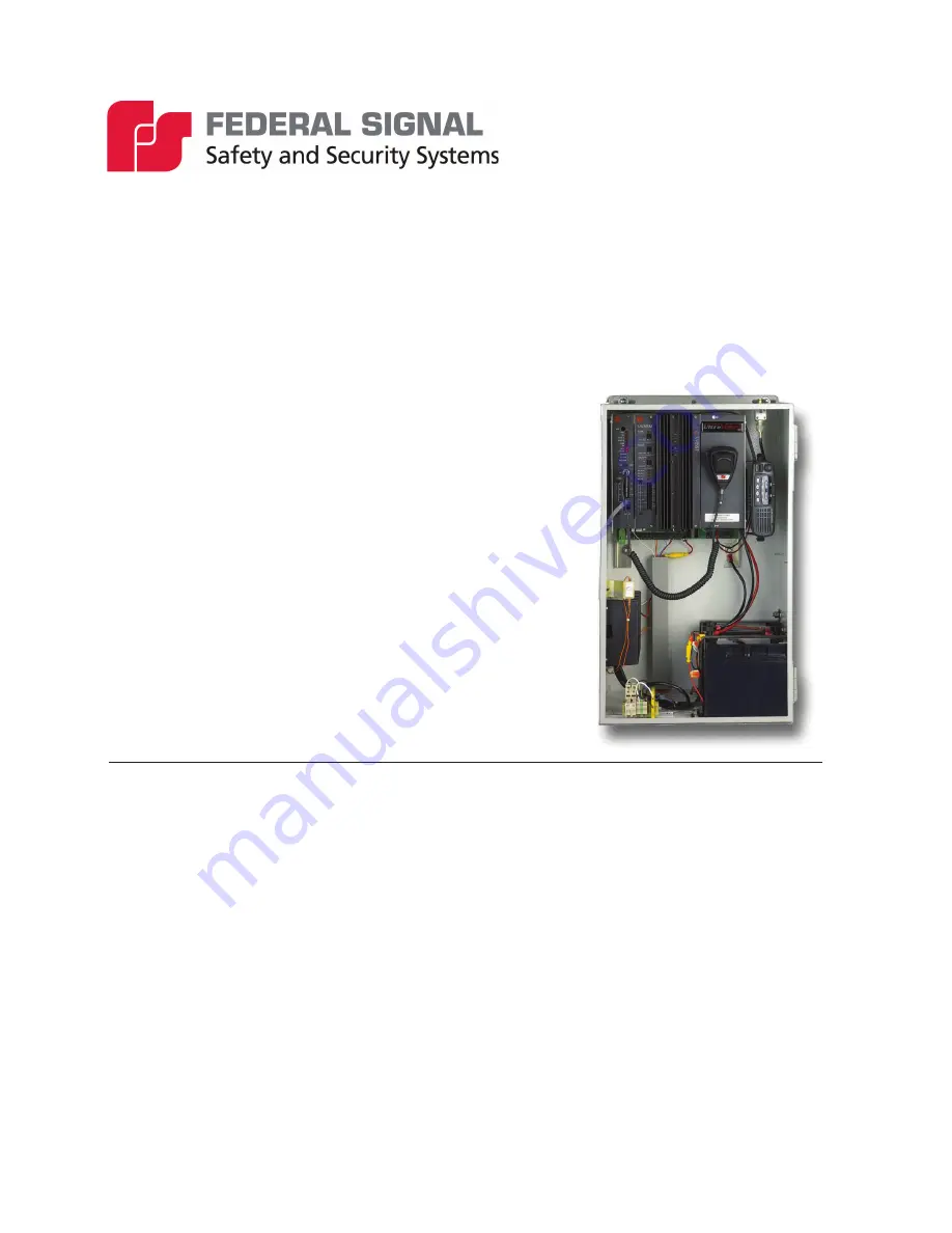
Page 23: ...23 Installation Description Specifications Installation Operation and Service Manual Figure 2 UVIC Cabinet Dimensional Outline Drawing Figure 3 UVIC Parts Layout...
Page 24: ...sembly To reduce the weight of the cabinet during installation do not install the batteries before mounting the cabinet 3 Prepare the mounting surface for hanging the cabinet by predetermining the loc...
Page 25: ...radio UVIC Installation Material List and Installation Guidelines The following material lists and guidelines describe basic installation details required to install the UVIC cabinet This list varies...
Page 26: ...rnal antenna applications Varies Concrete or Filled Cement Block Wall Mounting Guidelines Table 22 Concrete or Filled Cement Block Wall Mounting Materials Material Description Purpose Qty 3 8 x 3 in P...
Page 27: ...holes for the 3 8 by 3 inch lag bolts 7 Mount the cabinet to the mounting backboard 8 Proceed to the following section Metal Stud Wall Mounting Guidelines Table 25 Metal Stud Wall Mounting Materials...
Page 28: ...located on the cabinet door All other UVIC models are to be wired to 120 VAC DIN Rail Terminal Blocks These points provide a convenient location for making electrical connections Push a small screwdri...
Page 29: ...l or as otherwise specified by code 4 Connect one line wire from the 15 A breaker panel to the fused DIN rail mounted terminal block labeled F1 L1 in the UVIC cabinet 5 Connect the other line wire fro...
Page 30: ...IC is being installed in a very good RF coverage area you may use a cabinet Mounted Magnetic Base antenna 1 Connect the antenna cable to the antenna connector on the top of the UVIC cabinet 2 Mount th...
Page 31: ...r slot Install a UVIC25ST in the second slot Wire the connection between the amplifier and UVIC25ST using the included cable Use JP24 Amplifier 2 for all 25 V wiring connections See the figure below f...
Page 32: ...ctions and Wall Mounting See Figure 6 UVLOC Dimensional Outline and Figure 7 UVLOC Interface Wiring Diagram for the UVLOC mounting hole locations The UVLOC is typically mounted on a wall approximately...
Page 33: ...power is required to run external devices the UVIC has a large connector available labeled JP6 24 Vdc located behind the cover plate on the right side of the amplifiers This connector accepts bare st...
Page 34: ...place a jumper across pins 1 2 of JP8 Use R123 to control the volume level when used in this mode Provide a contact closure at JP15 pins 10 and 11 PTT Push To Talk to turn on the amplifiers and route...
Page 35: ...35 Installation Description Specifications Installation Operation and Service Manual Figure 8 UVIC Strobe and Speaker Wiring...
Page 36: ...ired purchase a 24 to 12 Vdc voltage converter This converter is provided with the UVIC series models Do not use one of the 12 Vdc batteries to run the radio equipment 1 AUDIO Connect the UV controlle...
Page 37: ...aker Pre Operation Checkout To conduct an amplifier and speaker pre operation checkout 1 See UVIC IP Wiring Diagram in Appendix B Measure the DC voltage between battery 1 and battery 2 The voltage sho...
Page 38: ...P16 UV controller card for 1 Vp p using the REC gain adjustment R105 controller card front panel See Figure 4 Adjusting the transmit deviation To adjust the transmit deviation 1 Simultaneously press b...
Page 39: ...it for approximately 8 seconds b Determine proper siren TX level required typically 1 Vp p or approximately 0 dB c The TX levels for all of the siren controllers must be the same d Verify the RX audio...
Page 40: ...rify the green power LED on the control panel is on 2 Turn the rotary selection switch fully counter clockwise to the LIVE P A position 3 Press the ARM button for 1 second and verify the red ARM LED t...
Page 41: ...or CPU Microprocessor heartbeat CARRIER Radio frequency RF carrier indicator ON with carrier present RX LEVEL 3 stage LED bar graph The following table provides the descriptions of the front panel con...
Page 42: ...ADDRESS LED COMPUTER CLOCK CARRIER DETECT LED MICROPHONE VOLUME ADJUSTMENT MICROPHONE JACK SIREN FUNCTION BUTTONS 2 WAY RADIO CONNECTOR RS232 SERIAL CONNECTOR OVER TEMPERATURE LED POWER LED POWER OUT...
Page 43: ...tion For activation to occur the location code of the received EAS message must match one of the three assigned codes You cannot program units for both Tone and EAS activation at the same time Therefo...
Page 44: ...Voice Plays a sequence of digital voice messages specified at the time of activation This function is only applicable for sirens equipped with a special vocabulary chip Public Address Broadcast live r...
Page 45: ...nction allows you flexibility in building alerting or other zone dependent systems You can divide each UV controller into eight different zones When selecting the Zone Control function you are prompte...
Page 46: ...ite 4 toggle the third dip switch to the left For Site 5 toggle the first and third dip switch to the left Continue this method to define other site number addresses Figure 10 Setting the Switch Numbe...
Page 47: ...o for JP1 output Short pins 2 and 3 to select channel B audio for JP1 output JP4 3 pin shorting jumper Short pins 1 and 2 to select channel A audio for JP3 output Short pins 2 and 3 to select channel...
Page 48: ...ication Connectors and Indicators for the Serial to Network PCB Table 34 Connectors for the Serial to Network PCB JP1 600 Ohm Audio Output Port Balanced line output To JP12 UVIC motherboard JP6 10 5 9...
Page 49: ...VEL OUTPUT POWER CPU 2005457_ GND DEFAULT 12V T1 JP1 JP7 JP5 JP2 JP3 JP4 JP6 J1 L1 291351A D4 D1 D3 D2 R1 Audio Out Audio Out Adjust To IP COMMS To Serial Interface Input Power Connectors for the Fron...
Page 50: ...to force Carrier Detect of External transceiver 1 JP13 Front Panel External Transceiver radio Connector Ports 1 and 2 JP14 Equalizer setting for public address or digital voice Setting is normal or t...
Page 51: ...1 ISO Ground 2 Spare 1 4 Intrusion 6 Solar 8 AC Power 10 600 Ohm PTT 12 Spare 2 JP16 Isolated Power Supply Pins 1 5 2 5 150 mA maximum current for external equipment JP17 Spare Sensor Input Pins 1 ISO...
Page 52: ...Amplifier 2 Output Pins 1 12 SIG JP24 Amplifier 2 Output Pins 1 12 SIG JP29 Expansion Port Primary Cabinet Pins 1 Ground 2 I2 C VCC 5 3 Serial Clock 1 4 Serial Data 1 5 Amplifier Audio Signal A 6 Ampl...
Page 53: ...53 Operations Description Specifications Installation Operation and Service Manual Table 39 Motherboard Outline Drawing...
Page 54: ...tes function 6 CODE 7 Activates function 7 STOP Reset CODE 1 and CODE 6 Loads default speaker calibration values and transmits DTMF characters production testing CODE 2 and CODE 3 Calibrate speaker lo...
Page 55: ...tatus monitoring of the unit over wire lines Also use this port to connect external audio sources to the amplification system See Figure 14 UVIC Controller Backplane Motherboard I O Remote Activation...
Page 56: ...ections JP15 JP15 Terminal Function 1 COM Common 2 SPR 1 Spare 1 3 COM Common 4 INTR Intrusion 5 COM Common 6 SOL Solar 7 COM Common 8 AC AC Power 9 COM Common 10 600 PTT 600 PTT 11 COM Common 12 SPR...
Page 57: ...Inputs JP17 The inputs at JP17 are not used in typical applications with the UVIC controller Two Way Sensor Package The two way sensor package uses a variety of sensors in the UVIC controller which w...
Page 58: ...l amplifier voltage and current are monitored with Quiet Test providing a true indication of each amplifier and load performance Finding Faults When using Commander the controller automatically update...
Page 59: ...ent or has a blown fuse or is not producing the correct output voltage NOTE Battery Voltage is temperature compensated when the temperature is above 86 F 30 C UVLOC Train all potential users on the us...
Page 60: ...for 1 second 2 Turn the dial to RECORD 3 Hold down the ACTIVATE button while speaking within 12 inches of the microphone and release button to stop recording RECORD re records the previous message eac...
Page 61: ...61 Operations Description Specifications Installation Operation and Service Manual Figure 17 UVLOC Drawing...
Page 62: ...ills confidence in the reliability of the system In order to minimize the potential for a failure annual inspection and maintenance is recommended General Maintenance Checking Signal Operational To ch...
Page 63: ...check signal indicators on amplifiers during a function If indicators are off remove amplifier for service Function stops before normal timeout Batteries may require further charging Check battery vo...
Page 64: ...difficulties contact Federal Signal Customer Support at 800 548 7229 or 708 534 3400 extension 7511 or Technical Support at 800 524 3021 or 708 534 3400 extension 7329 or through e mail at techsupport...
Page 65: ...adio Information complete this section for install commissioning maintenance N A 25 Radio Make 26 Radio Model 27 Comm Mode Analog P25 Digital Type 28 Trunking Yes No 29 BW 25 12 5 6 25 30 CH1 RTU Tx R...
Page 66: ...ned Cabinets Yes No 94 Desiccant in Control Cabinet Yes No 95 Antenna installed per manual Yes No 96 Antenna Connectors Sealed Yes No 97 Pole installed per manual Yes No 98 Backfill of Hole Site clean...
Page 67: ...67 Appendix B Drawings Figure 18 UVIC Wiring Diagram...
Page 68: ...68 Figure 19 UVIC IP Wiring Diagram...
Page 69: ...69 Figure 20 UVIC LL Wiring Diagram...
Page 70: ...NOB THREADED STUD M6 4 7159100A NUT HEX HD M6X1 0 SS 1 T300108 10 008 T WIRE 4 5 1 8291B013 BAG POLY 5X7 4 167106A FOOT BUMPON MATERIAL DESCRIBED AND INFORMATION CONVEYED IS PROPRIETARY TO FEDERAL SIG...