background image

6

CAUTION

THE TXV SENSING BULB CAN BE DAMAGED BY

EXTREME HEAT FROM BRAZING. THE BULB SHOULD
BE REMOVED BEFORE PERFORMING ANY BRAZING
PROCEDURE AND NOT INSTALLED UNTIL AFTER THE
VAPOR AND LIQUID LINES ARE BRAZED AND LEAK
CHECKED.

Connect Refrigerant Piping

Use field supplied tubing of refrigerant grade. Suction tube
must be insulated. Do not use damaged, dirty, or
contaminated tubing because it may plug refrigerant flow
control device. ALWAYS evacuate the coil and field supplied
tubing before opening outdoor unit service valves. 

Factory and Field-Installed Expansion Valves

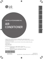
1.  The bulb and capillary tubing should be routed outside

of the case. Make sure the capillary tube will not contact
any sharp edges of the case. On factory installed
expansion valves, the adjustable sensing bulb is not
permanently installed onto the coils’ vapor line in order
to allow easy removal during installation.

4 o’clock

8 o’clock

Sensing bulb
attached with
clamps

Vapor line

4 o’clock

8 o’clock

Attach bulb to
vapor line at four
or eight o’clock
position

CAUTION

THE TXV VALVE CAN BE DAMAGED BY EXTREME

HEAT. PROPER PRECAUTIONS SHOULD BE TAKEN TO
AVOID OVERHEATING THE TXV VALVE AND CAUSING
DAMAGE TO THE INTERNAL COMPONENTS.

3.  Attach the bulb securely with the copper strap provided.

4.  Insulate the bulb thoroughly with a suitable insulation

material such as cork tape.

5. Coils with TXVs should be charged 10-12 degrees 

(+ or – one degree) of sub-cooling. This supercedes any
subcooling value listed with condensing unit’s literature. 

For the majority of installations no adjustment to the
TXV setting is required. However, if the measured
superheat is less than 4° or greater than 8° an
adjustment is required. The adjustment stem is at the
base of the valve under the flare nut. To increase
superheat, tighten the stem clockwise and to decrease
superheat, back-out the stem counter-clockwise. Use a

1/4

” refrigeration service wrench for this function.

NOTE: 

When removing refrigerant, always use standard reclaim
procedures.

2. To assure accurate sensing and the best performance the

bulb should be placed on a horizontal section of the
vapor line at the four or eight o’clock position and at
least 6” from the coil manifold.

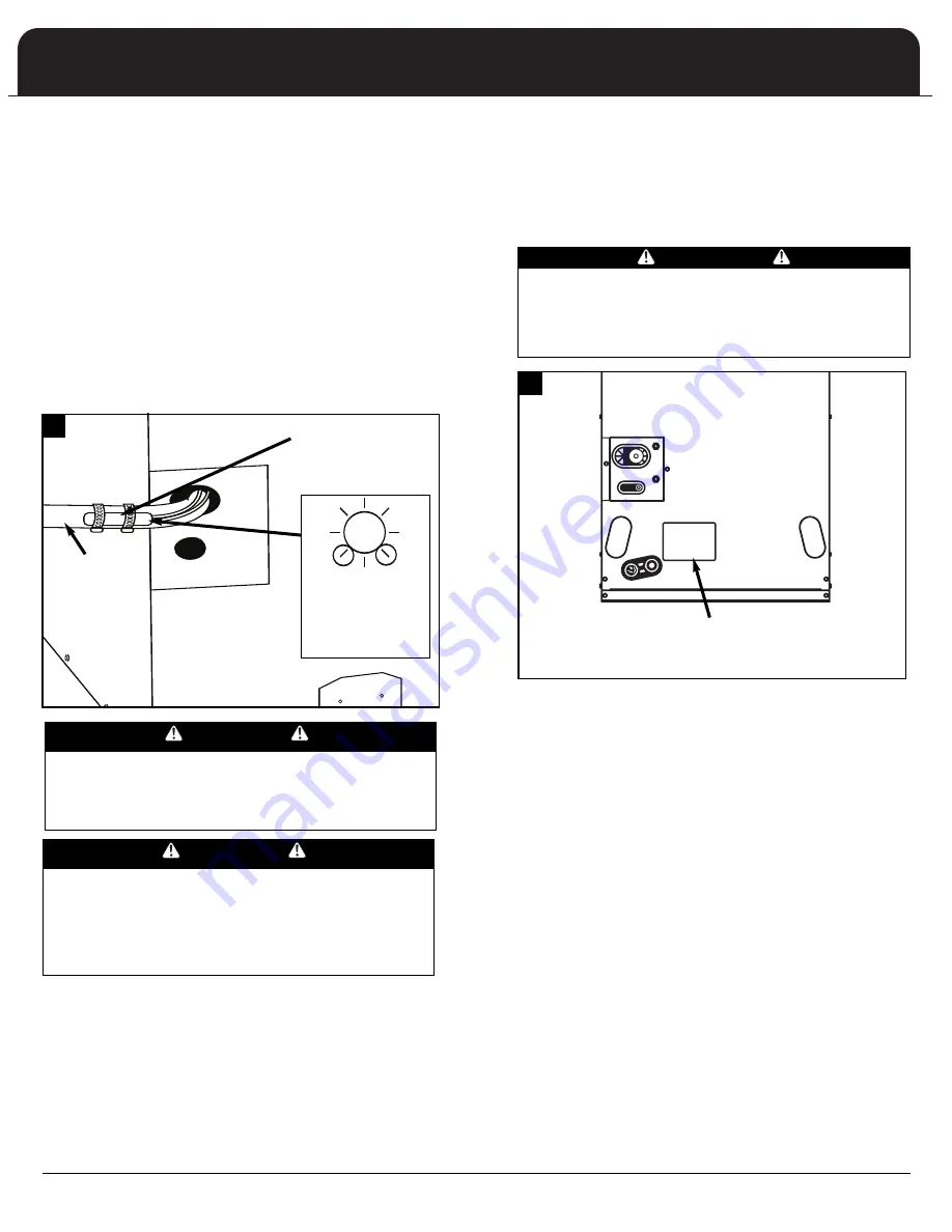
TXV valve can be accessed
through the valve cover-plate
on the front of the air handler.

WARNING

ALWAYS HAVE A FIRE EXTINGUISHER AVAILABLE
WHEN WORKING WITH AN OPEN FLAME.

ALWAYS USE SAFETY GLASSES, PROTECTIVE
CLOTHING, AND WORK GLOVES.

11

7

11

6

Summary of Contents for AFPB24B1

Page 1: ...ing 6 Factory and Field installed Expansion Valves 6 Ductwork 7 Return Air Ducting 7 Return Air Platform Height 7 LINE VOLTAGE CONNECTIONS 7 24 VOLT CONTROL SYSTEM 8 CONDENSATE PLUMBING 8 WIRING DIAGR...

Page 2: ...ion which if not avoided could result in death or serious injury CAUTION indicates a potentially hazardous situation which if not avoided may result in minor or moderate injury CAUTION used without th...

Page 3: ...ndividuals specially trained and experienced in the installation of this type equipment and related system components Installation and service personnel are required by some locales to be licensed Per...

Page 4: ...E DUCT 600 FPM 24 MINIMUM RETURN GRILLE 500FPM RETURN PLATFORM LINED WITH 1 FIBERGLASS INSULATION REFER TO LOCAL CODES CLOSET AIR HANDLER Upflow Installation With Return Duct DISCHARGE DUCT 600 FPM 24...

Page 5: ...rom left hand side of air handler and re install on right hand side Change splash baffle location from left hand to right hand side of drain pan flange 4 Remove the horizontal coil support bracket fro...

Page 6: ...filter grille may be installed for closet applications If this method is not desirable cabinet extension kit No 65 1647 for A24 A30 and A36 or No 65 1649 for A42 A48 and A60 may be ordered The extens...

Page 7: ...BE TAKEN TO AVOID OVERHEATING THE TXV VALVE AND CAUSING DAMAGE TO THE INTERNAL COMPONENTS 3 Attach the bulb securely with the copper strap provided 4 Insulate the bulb thoroughly with a suitable insu...

Page 8: ...4 2 5 163 8 41 6 221 4 56 5 3 7 6 3 7 6 13 4 4 4 2 5 163 8 41 6 221 4 56 5 3 7 6 3 7 6 13 4 4 4 2 5 11 8 WARNING BEFORE PERFORMING ANY WORK ON THIS EQUIPMENT POWER SUPPLY MUST BE TURNED OFF AT THE HOU...

Page 9: ...ING IMPROPER INSTALLATION OF THE ELECTRICAL WIRING OR THE HEAT ASSEMBLY MAY RESULT IN FIRE SERIOUS PERSONAL INJURY OR DEATH UNIT FLEXIBLE TUBING HOSE OR PIPE DRAIN CONNECTION A POSITIVE LIQUID SEAL IS...

Page 10: ...0 5 3 10 5 3 kW does not include motor watts Ampacities and over current protection based on largest air handler motor load Refer to specific name plate for exact ampacity and overcurrent protection s...

Page 11: ...1 4 3 5 8 13 1 4 15 48 1 8 19 1 8 21 26 22 16 3 8 22 1 4 AFPC48B1 2 1 4 3 5 8 13 1 4 15 48 1 8 19 1 8 21 26 22 16 3 8 22 1 4 AFPC60A1 2 1 4 3 5 8 13 1 4 15 48 1 8 19 1 8 21 26 22 16 3 8 22 1 4 AFPC60B...

Page 12: ...30 1840 1770 1590 LOW 20 kW 0 35 15 kW 0 35 1360 1350 1340 1185 1080 Air flow shown at the following conditions No heat elements in air handler Decrease CFM 1 for 5 kW 7 5 kW or 10 kW heat kits Decrea...

Page 13: ...ompartment remove the cover plate from the element housing Remove cover plate Remove air handler field wiring box and discard Remove two screws 11 14 11 15 5 Cut the wire tie holding the heater plug a...

Page 14: ...other than 230 multiply temperature rise by capacity correction factor Refer to CFM tables to determine Cfm at total external static pressure in system For correction of unit output multiply the corr...

Page 15: ...TATIONS Limited Warranty does not include allowances for labor or travel expense connected with the installation of parts so furnished in this Limited Warranty or for field repair or servicing of the...

Page 16: ...r the general appearance of the units at the time of publication and the manufacturer reserves the right to make changes in design and construction at any time without notice For replacement parts ple...

Reviews: