background image

4.

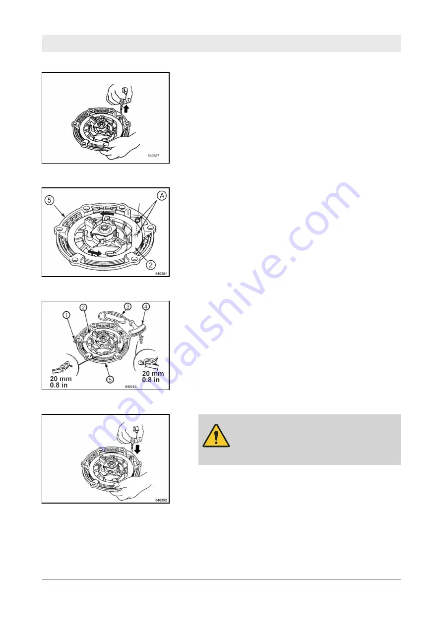
Pull the starter rope with the starter handle out completely.

5.

If the starter rope has been torn or the coil has recoiled com-

pletely:

n

Before assembling the rope, turn the coil (2) 5 revolutions

in anti-clockwise direction and align the rope openings in

coil and housing (5) to one another (A).

6.

Secure the coil against winding up. For this purpose tie the

coil (2) to the housing (5) with a cable strap (1).

7.

Untie the knots of the starter rope at both ends and remove

the old starter rope.

8.

Thread in the new starter rope (3) and fix it with knots on

both ends.

9.

CAUTION!
Danger of injury caused by the starter

handle hitting against your body!

Do not let the starter handle hit back.

Remove the fixing of the coil and run the starter handle

slowly back to initial position.

10.

Pull the starter handle to check the function and light move-

ment of the recoil starter.

Fig.  88

Fig.  89

Fig.  90

Fig.  91

Maintenance – Annually


DFP9


87

Summary of Contents for Dynapac DFP9

Page 1: ...Operating Instruction Maintenance Instruction Original Operating Instructions DFP9 Forward plate S N 961 925 33 1001 S N 861 925 33 1001 DL8 204 94 EN 02 2020 ...

Page 2: ...uding toluene and benzene which are known to the State of California to cause cancer and birth defects or other reproductive harm WARNING Breathing diesel engine exhaust exposes you to chemicals known to the State of California to cause cancer and birth defects or other reproductive harm Always start and operate the engine in a well ventilated area If in an enclosed area vent the exhaust to the ou...

Page 3: ...2 3 3 3 Modifications and alterations to the machine 22 3 3 4 Damage defects misuse of safety devices 22 3 4 Handling fuels and lubricants 23 3 4 1 Preliminary remarks 23 3 4 2 Safety regulations and environmental protection regulations for handling gasoline 24 3 4 3 Safety regulations and environmental protection regulations for handling fuel stabiliser 25 3 4 4 Safety regulations and environment...

Page 4: ...rs 50 5 6 Checking the water level topping up 51 6 Operation 53 6 1 Mounting the guide handle 54 6 2 Starting the engine 55 6 3 Operation 58 6 4 Switching the water spraying system on off 60 6 5 Parking the machine in secured condition 61 7 Loading transporting the machine 63 7 1 Loading the machine 64 7 2 Lashing the machine to the transport vehicle 65 7 3 Transport wheels 66 8 Maintenance 67 8 1...

Page 5: ...r housing 88 8 9 As required 90 8 9 1 Cleaning the cooling fins and the cooling air intake openings 90 8 9 2 Cleaning the machine 91 8 9 3 Cleaning the water spraying system 92 8 9 4 Servicing the V belt 92 8 9 5 Checking cleaning the spark plug 93 8 9 6 Measures if there is a risk of frost 94 8 9 7 Measures prior to extended shut down period 94 9 Troubleshooting 97 9 1 Preliminary remarks 98 9 2 ...

Page 6: ...Table of contents DFP9 6 ...

Page 7: ...1 Introduction Introduction DFP9 7 ...

Page 8: ...ting maintenance and repair measures to maintain the functional safety of your machine A description of all necessary maintenance work maintenance intervals as well as information on fuels and lubricants can be found in the chapter Maintenance Ä Chapter 8 Maintenance on page 67 Do not service or repair your machine by yourself to avoid harming persons or damaging material or environment The machin...

Page 9: ...ot constitute an extension of the warranty and liability conditions specified in the general sales and delivery conditions of Dynapac GmbH We wish you successful work with your Dynapac machine Introduction Foreword DFP9 9 ...

Page 10: ...e Engine type Engine number Made by Designation Type Nominal Power Operating Mass Year of Construction Serial No Made in Germany Ammerländer Str 93 D 26203 Wardenburg 1 2 B 924 0001 Fig 1 Machine type plate example Engine type and engine number Fig 2 Introduction Machine type plate and engine type plate DFP9 10 ...

Page 11: ...2 Technical data Technical data DFP9 11 ...

Page 12: ...0 17 7 Dimensions in millimetre Dimensions in inch Weights Operating weight CECE 91 201 kg lbs Basic weight 90 198 kg lbs Water spraying system optional equipment 7 15 4 kg lbs Transport wheels optional equipment 4 8 8 kg lbs Dimensions Technical data DFP9 12 ...

Page 13: ...ed power SAE J 1349 3 6 4 8 kW hp Rated speed 3600 min 1 Drive system mechanical Exciter system Frequency 90 5400 Hz vpm Centrifugal force 18 4050 kN lbf amplitude 1 63 0 064 mm in Water sprinkling system optional equipment Type of sprinkling Gravity feed Filling capacities Fuel gasoline 3 1 0 8 each l gal us Sprinkling system water 7 0 1 9 each l gal us Technical data DFP9 13 ...

Page 14: ...mined acc to ISO 3744 and EN 500 2 1 2 Vibration data Vector total of the weighted effective acceleration in three orthog onal directions Total vibration value ahv 7 9 m s2 on crushed rock determined acc to EN 500 ISO 5349 Associated uncertainty K 1 9 m s2 determined acc to EN 12096 Observe the daily vibration load work safety acc to 2002 44 EC Vector total of the weighted effective acceleration i...

Page 15: ...3 Concerning your safety Concerning your safety DFP9 15 ...

Page 16: ...ns n generally accepted safety and road traffic regulations n country state specific safety regulations It is the duty of the operator to be acquainted with the safety regu lations and to apply these accordingly This also applies for local regulations and regulations concerning different types of handling activities Should the recommendations in these instructions be dif ferent from the regulation...

Page 17: ...ractices for safe and environment friendly disposal of fuels and lubricants as well as replacement parts 3 1 3 Personal protective equipment Depending on the work to be carried out personal protective equipment is required to be provided by the operating company Working clothes Tight fitting working clothes with low tear resistance tight sleeves and without any projecting parts protect against bei...

Page 18: ... use This machine must only be used for n Compaction of all types of soils n Repair work on all types of soil n Paving of walkways n Work in trenches n Underfilling and compaction of hard shoulders Intended use also includes compliance with the specified oper ating maintenance and repair measures 3 1 5 Improper use Dangers may arise from the machine when it is used for purposes other than the one ...

Page 19: ...ing and lashing points specified in these instructions must be used It is prohibited to use other lifting and lashing points e g guide handle steering rod 3 1 6 Estimated service life of the machine If the following general conditions are met the service life of the machine is usually in the range of several thousand operating hours n Regular safety inspections by an expert qualified person n Perf...

Page 20: ...f regular safety inspections 3 2 2 Expert qualified person An expert qualified person is a person who based on his her pro fessional education and experience has profound knowledge in the field of construction equipment and the machine in question in particular This person is acquainted with the applicable governmental indus trial safety regulations accident prevention instructions guidelines and ...

Page 21: ... operate the machine Persons under the influence of alcohol medication or drugs are not allowed to operate service or repair the machine Maintenance and repair work requires specific knowledge and must therefore only be performed by trained specialists Concerning your safety Definition of responsible persons DFP9 21 ...

Page 22: ...st be informed about the dangers that arise from the operation of the machine 3 3 2 Regular safety inspections Have the machine inspected by an expert qualified person as required for the conditions the machine is working under but at least once every year 3 3 3 Modifications and alterations to the machine Unauthorized changes to the machine are prohibited for safety rea sons Original parts and ac...

Page 23: ...n name of substance n possible dangers n composition information on constituents n first aid measures n fire fighting measures n measures in case of accidental release n handling and storage n limitation and monitoring of exposure personal protective equipment n physical and chemical properties n stability and reactivity n toxicological data n environmental data n notes on waste disposal n informa...

Page 24: ...G Health hazard caused by contact with gasoline Wear your personal protective outfit protective gloves protective clothing Do not inhale any fuel fumes Do not swallow gasoline Avoid contact with gasoline ENVIRONMENT Gasoline is an environmentally hazardous sub stance Always keep gasoline in proper containers Immediately bind spilled gasoline with an oil binding agent and dispose of in accordance w...

Page 25: ... with fuel sta bilizer Wear your personal protective outfit protective gloves protective clothing Do not inhale any fuel stabilizer fumes Do not swallow fuel stabilizer Avoid contact with fuel stabilizer ENVIRONMENT Fuel stabilizer is an environmentally hazardous substance Immediately bind spilled fuel stabilizer with an oil binding agent and dispose of according to regulations Dispose of fuel sta...

Page 26: ... caused by contact with oil Wear your personal protective equipment pro tective gloves protective clothing Do not inhale any oil vapours Avoid contact CAUTION Danger of slipping on spilled oil Immediately bind spilled oil with an oil binding agent ENVIRONMENT Oil is an environmentally hazardous substance Always keep oil in proper containers Immediately bind spilled oil with an oil binding agent Di...

Page 27: ...hine components Secure the machine on the transport vehicle against rolling slip ping and turning over Loads must only be attached and hoisted by an expert capable person Use only lifting gear and lifting tackle with sufficient load bearing capacity for the weight to be loaded Fasten the lifting gear only at the specified lifting points Danger to the life of persons if they step or stand under a s...

Page 28: ...r other faults the machine must not be operated until these deficiencies have been corrected Do not operate the machine with defective indicators and control elements 3 6 2 Spark protection The spark protection is optional In some areas of use operation of an engine without spark protec tion is not permitted Check the locally valid legislation and regulations 3 6 3 Starting the engine Do not use a...

Page 29: ...Avoid operation in closed or partly closed rooms or ensure ade quate ventilation when working in trenches Concerning your safety Start up procedure DFP9 29 ...

Page 30: ...sual noises and development of smoke Perform trouble shooting and have the fault corrected Always keep a safe distance to excavation pit borders embank ments and edges Refrain from any work that could adversely affect the stability of the machine Observe the daily vibration load work safety acc to 2002 44 EC 3 7 3 Parking the machine Park the machine on horizontal level firm ground Before leaving ...

Page 31: ...nition and heat sources Apply measures against electrostatic charging Do not spill any fuel Collect leaking fuel do not let it seep into the ground Wipe off spilled fuel Keep dirt and water away from the fuel A leaking fuel tank can cause an explosion Ensure tight fit of the cover if necessary replace immediately Concerning your safety Refuelling DFP9 31 ...

Page 32: ...ters and other oil contaminated materials in a sepa rate specially marked container and dispose of environmentally 3 9 3 Cleaning work Do not perform cleaning work while the motor is running Allow the engine to cool down before starting cleaning work Do not use gasoline or other easily inflammable substances for cleaning 3 9 4 Measures for longer shut down periods If the machine is taken out of op...

Page 33: ...s been repaired When replacing safety relevant components only original spare parts must be used Repairs must only be performed by an expert qualified person When performing welding work on the machine you should cover the fuel tank with insulating material Concerning your safety Repair DFP9 33 ...

Page 34: ...efore taking into operation vor Inbetriebnahme avant la mise en service anterior a la puesta en servicio weekly wöchentlich hebdomadairement cada semana twice annual halbjährlich tous les 6 mois cada 6 meses annual jährlich annuellement anualmente BENZIN GASOLINE WARNING California Proposition 65 Warning This product contains chemicals that cause cancer chemicals that are reproductive toxicants I ...

Page 35: ...uction sticker Wear ear defenders Information sticker Guaranteed sound capacity level Fig 7 WARNING California Proposition 65 Warning This product contains chemicals that cause cancer chemicals that are reproductive toxicants B DEC 0316 Fig 8 Fig 9 Fig 10 Concerning your safety Signage DFP9 35 ...

Page 36: ...Information sticker Lifting point Information sticker Filler opening for petrol Information sticker Filler opening for water Fig 11 Fig 12 B DEC 0216 Gasoline Benzin Fig 13 B DEC 0218 Water Fig 14 Concerning your safety Signage DFP9 36 ...

Page 37: ...bnahme avant la mise en service anterior a la puesta en servicio weekly wöchentlich hebdomadairement cada semana twice annual halbjährlich tous les 6 mois cada 6 meses annual jährlich annuellement anualmente BENZIN GASOLINE B DEC 0276 Fig 16 Made by Designation Type Nominal Power Operating Mass Year of Construction Serial No Made in Germany Ammerländer Str 93 D 26203 Wardenburg B 924 0002 Fig 17 C...

Page 38: ...3 12 Safety components 1 2 B 834 0293 Fig 18 1 Heat protection cover 2 Belt guard Concerning your safety Safety components DFP9 38 ...

Page 39: ...4 Indicators and control elements Indicators and control elements DFP9 39 ...

Page 40: ...view Fig 19 1 Engine stop switch 2 Throttle lever 3 Choke lever 4 Recoil starter 5 Fuel valve 4 1 2 Engine stop switch Position OFF Ignition off Position ON Ignition on Fig 20 Indicators and control elements Engine DFP9 40 ...

Page 41: ...IN Idle speed Position MAX Maximum speed 4 1 4 Choke lever Position Left Choke closed Position Right Choke open 4 1 5 Recoil starter B HON 0041 Fig 21 B HON 0042 Fig 22 B GEN 0084 Fig 23 Indicators and control elements Engine DFP9 41 ...

Page 42: ...4 1 6 Fuel valve Position Left Fuel valve closed Position Right Fuel valve open B HON 0043 Fig 24 Indicators and control elements Engine DFP9 42 ...

Page 43: ...raying system 4 2 1 Shut off valve Position 0 Water spraying system off turn anticlockwise Water spraying system on infinite adjustment of the spraying quan tity up to MAX position Fig 25 Fig 26 Indicators and control elements Water spraying system DFP9 43 ...

Page 44: ...4 3 Transport wheels Fig 27 1 Locking of guide handle 2 Locking of transport wheels Indicators and control elements Transport wheels DFP9 44 ...

Page 45: ...5 Checks prior to start up Checks prior to start up DFP9 45 ...

Page 46: ...ixed settings WARNING Health hazard caused by fuels and lubricants Safety regulations and environmental protec tion regulations must be followed when han dling fuels and lubricants Ä Chapter 3 4 Han dling fuels and lubricants on page 23 WARNING Danger of injury caused by rotating parts Before starting work on the machine make sure that the engine can not be started 1 Park the machine safely Ä Chap...

Page 47: ...k and fuel lines and for leaks 2 Check the bolted connections are tight and secure 3 Check the machine for contamination and damage 4 Check the hydraulic oil cooler for dirt 5 Check the starter rope for chafing Checks prior to start up Visual inspections and function tests DFP9 47 ...

Page 48: ...ipstick and wipe it clean with a lint free clean cloth 3 Insert the dipstick into the oil filler socket do not screw it in but pull it out again to check the oil level ð The oil level must be between the MIN and MAX marks 4 NOTICE Danger of engine damage Do not fill in too much engine oil If the oil level is too low top up oil to the MAX mark 5 Screw the oil dipstick in B SYM 1068 Fig 28 B 834 002...

Page 49: ...on or even damage of the engine If necessary fill in fuel through a screen filter Use only fuel of the permitted specification Ä Chapter 8 2 2 Fuel on page 69 Protective equipment n Working clothes n Safety shoes n Protective gloves 1 Park the machine safely Ä Chapter 6 5 Parking the machine in secured condition on page 61 2 Clean the area around the filling port 3 Remove the cap and check the fil...

Page 50: ...lothes n Safety shoes n Protective gloves 1 Check the rubber buffer pairs left and right for tight fit cracks and tear offs ð Replace damaged rubber buffers immediately B SYM 1073 Fig 32 B 834 0081 Fig 33 Checks prior to start up Checking the rubber buffers DFP9 50 ...

Page 51: ...gloves 1 Clean the area around the filling port 2 Remove the cap 1 and check the water supply in the water tank 3 If necessary fill in clean water 4 Close the cap Alternatively the water tank can also be removed and transported for filling 1 Close the shut off valve 1 2 Loosen the hose clamp and pull the hose 2 off the shut off valve 3 Lift off the water tank upwards B 834 0224 Water 1 Fig 34 B 83...

Page 52: ...Checks prior to start up Checking the water level topping up DFP9 52 ...

Page 53: ...6 Operation Operation DFP9 53 ...

Page 54: ...ing screws Insert the fastening screws from the inside so that the guide handle can be folded down completely 2 Force the guide handle apart and plug it onto the holding fix tures 3 Lock and secure the guide handle on both sides with split pins Fig 36 Fig 37 Operation Mounting the guide handle DFP9 54 ...

Page 55: ...ng on hot components Wear your personal protective equipment pro tective gloves protective clothing Avoid touching hot components WARNING Loss of hearing caused by too high noise bur dens Wear your personal protective equipment ear protection Operate the machine only with the guide handle mounted and low ered Protective equipment n Hearing protection n Working clothes n Protective gloves n Safety ...

Page 56: ...pera tures are high the choke must remain open to prevent the engine from stalling Close the choke 5 Set the throttle lever to MIN position 6 Switch the engine stop switch to ON position B HON 0035 Fig 38 B HON 0037 Fig 39 B 230 0096 MAX MIN Fig 40 B 834 0079 ON OFF I 0 Fig 41 Operation Starting the engine DFP9 56 ...

Page 57: ...uring the first attempt repeat the starting process 12 Open the choke bit by bit when the engine is running 13 Run the engine warm for approx 1 to 2 minutes in idle speed NOTICE Danger of engine damage Warm up engine for a short while before starting work Do not operate the engine immediately under full load 14 If the engine stops again after approx 3 to 5 seconds n Close the choke again n Repeat ...

Page 58: ...ng on hot components Wear your personal protective equipment pro tective gloves protective clothing Avoid touching hot components WARNING Loss of hearing caused by too high noise bur dens Wear your personal protective equipment ear protection Protective equipment n Hearing protection n Working clothes n Protective gloves n Safety shoes 1 Make sure that no persons are in the danger zone 2 NOTICE Th...

Page 59: ...he machine by means of the guide handle 4 For short work interruptions you should always return the throttle lever to MIN position idle speed ð Vibration is switched off Fig 46 Fig 47 Operation Operation DFP9 59 ...

Page 60: ...system must be switched on and off by the shut off valve Position 0 Water spraying system off turn anticlockwise Water spraying system on infinite adjustment of the spraying quantity up to MAX position Fig 48 Operation Switching the water spraying system on off DFP9 60 ...

Page 61: ...ng protection n Working clothes n Protective gloves n Safety shoes 1 Park the machine on level and firm ground 2 Set the throttle lever to MIN position idle speed 3 NOTICE Danger of engine damage Do not shut down the engine all of a sudden from full load speed but let it idle for about two minutes Switch the engine stop switch to OFF position ð The engine is shut down B 834 0017 MAX MIN 1 2 Min Fi...

Page 62: ...4 Close the fuel valve completely 5 Secure the machine against unauthorised use B HON 0036 Fig 51 Operation Parking the machine in secured condition DFP9 62 ...

Page 63: ...7 Loading transporting the machine Loading transporting the machine DFP9 63 ...

Page 64: ... not be damaged by machine components When lifting the machine avoid uncontrolled movements of the load If necessary hold the load with guide ropes Protective equipment n Working clothes n Protective gloves 1 Park the machine in secured condition Ä Chapter 6 5 Parking the machine in secured condition on page 61 2 Allow the engine to cool down 3 Fold the guide handle forwards 4 Attach the lifting t...

Page 65: ...plication Lifting tackle must not be damaged by machine components Protective equipment n Protective gloves 1 Fold down the guide handle 2 Pull at least two suitable lashing belts crosswise across the marked lashing point 3 Lash the machine securely to the transport vehicle as shown 4 Use suitable gear to prevent the guide handle from swinging over unintentionally Fig 54 Loading transporting the m...

Page 66: ... guide handle with the locking bolts 1 3 Unlock the locking bolt 2 and fold down the transport wheels 4 Push the machine up by the guide handle and fold the trans port wheels under the base plate ð The machine can now be moved 1 2 B 834 0225 Fig 55 B 834 0226 Fig 56 Loading transporting the machine Transport wheels DFP9 66 ...

Page 67: ...8 Maintenance Maintenance DFP9 67 ...

Page 68: ...ive equipment Do not touch hot components Park the machine on horizontal level firm ground Perform maintenance work only with the engine shut down and the spark plug connector disconnected Make sure that the engine cannot be accidentally started during maintenance work Thoroughly clean machine and engine before starting maintenance work Do not leave any tools or other objects that could cause dama...

Page 69: ...ine oil espe cially under low ambient temperatures SAE 10W 30 is recommended for general use You may alternatively use 15W 40 except under low tempera tures 8 2 1 3 Oil change intervals Oil change interval semi annually or every 100 operating hours 8 2 2 Fuel 8 2 2 1 Fuel quality Use unleaded gasoline with a research octane number of 91 or higher or octane number 86 or higher Use unleaded standard...

Page 70: ...e Please follow the instructions of the manufacturer concerning the correct mixing ratio and shelf life Mixing in fuel stabilizer does not regenerate old fuel 8 2 3 Oil for exciter shaft housing Use only engine oils according to the following specifications n API CI 4 or higher quality Avoid mixing engine oils NOTICE Components may get damaged Do not use low ash engine oils for the exciter shaft h...

Page 71: ...tion Ä Chapter 8 2 2 Fuel on page 69 3 1 l 0 8 gal us Fuel stabilizer Specification Ä Chapter 8 2 2 2 Fuel stabil izer on page 70 DL 009 940 20 as required Exciter shaft housing SAE 10W 40 Specification Ä Chapter 8 2 3 Oil for exciter shaft housing on page 70 Components may get damaged Do not use low ash engine oils for the exciter shaft housing 0 25 l 0 07 gal us SAE 15W 40 SAE 10W 30 Water tank ...

Page 72: ... engine oil Ä Chapter 8 7 1 Changing the engine oil on page 77 2 Check engine and machine for leaks 3 Retighten the fastening screws on air filter exhaust and other attachments 4 Retighten the bolted connections on the machine 5 Checking the V belt Ä Chapter 8 9 4 Servicing the V belt on page 92 6 Check the oil level in the vibrator housing Maintenance Running in instructions DFP9 72 ...

Page 73: ... fuel strainer 82 8 8 5 Replacing the air filter 85 8 8 6 Replacing the starter rope 86 8 8 7 Changing the oil in the exciter housing 88 As required 8 9 1 Cleaning the cooling fins and the cooling air intake openings 90 8 9 2 Cleaning the machine 91 8 9 3 Cleaning the water spraying system 92 8 9 4 Servicing the V belt 92 8 9 5 Checking cleaning the spark plug 93 8 9 6 Measures if there is a risk ...

Page 74: ...torch Do not continue to use a damaged air filter ele ment If in doubt use a new air filter Protective equipment n Working clothes n Safety shoes n Protective gloves n Safety goggles 1 Park the machine safely Ä Chapter 6 5 Parking the machine in secured condition on page 61 2 Allow the engine to cool down 3 Unscrew wing nut 1 and remove cover 2 4 Clean the cover 5 Unscrew wing nut 3 and remove fil...

Page 75: ... by moving the gun up and down inside the element until it is free of dust 9 In case of excessive dirt replace the paper element 10 Clean the foam element 5 in warm soapy water rinse it and let it dry thoroughly 11 Soak the foam element in clean engine oil and press exces sive oil out 12 Check both elements thoroughly for holes and cracks 13 Replace if damaged 14 Pull the foam rubber element over ...

Page 76: ...r seal 5 16 Insert the filter element 4 correctly and tighten it with the wing nut 3 17 Tighten the cover 2 with the wing nut 1 18 Dispose of the filter element if replaced in an environmen tally friendly way Assembling the air filter B HON 0033 1 2 3 4 5 Fig 62 Maintenance Weekly DFP9 76 ...

Page 77: ...on hot components Wear your personal protective equipment protective gloves protective clothing Avoid touching hot components Clean the area around oil dipstick 1 and drain plug 3 3 Unscrew the oil dipstick 4 Unscrew the drain plug and collect any oil running out 5 Clean the oil drain plug and screw it back in with a new seal ring 2 6 Fill in fresh oil up to the bottom edge of the filler bore 7 Pu...

Page 78: ...park plug using a 13 16 inch spark plug spanner 5 Check the electrode gap of the new spark plug with a feeler gauge if necessary adjust the gap ð Nominal value 0 7 0 8 mm 0 028 0 032 in 6 Screw in the new spark plug carefully by hand 7 Once the sealing surface of the new spark plug is in contact tighten for another 1 2 turn with the spark plug spanner 8 8 2 Checking adjusting the valve clearance P...

Page 79: ...th seal 3 5 Set the piston to the top dead centre position of the compres sion stroke For this purpose align the alignment mark 2 on the starter disc to the top bore 1 Valve clearance Intake valve IN 0 08 mm 0 003 in Exhaust valve EX 0 10 mm 0 004 in 1 Check the valve clearance with a feeler gauge between rocker arm 2 and valve shaft 1 on both valves adjust if necessary Preparations Fig 67 Fig 68 ...

Page 80: ...stening screws 1 evenly 3 After a short test run check the engine for leaks 8 8 3 Replacing the V belt Protective equipment n Working clothes n Safety shoes n Protective gloves 1 Park the machine safely Ä Chapter 6 5 Parking the machine in secured condition on page 61 2 Allow the engine to cool down 3 Loosen the fastening screws 2 and remove the V belt guard 1 Adjusting the valve clearance Fig 70 ...

Page 81: ...8 Check tension of V belt tighten if necessary ð Compression measurement approx 5 mm 0 2 in 9 Assemble the V belt guard 1 with fastening screws 2 10 Check the V belt tension again after 25 operating hours tighten if necessary 8 8 3 1 Checking the frequency of the base plate Keep feet and hands clear of the vibrating base plate 2 B 834 0170 1 Fig 73 1 B 834 0171 Fig 74 Fig 75 B 834 0144 1 2 Fig 76 ...

Page 82: ...Park the machine safely Ä Chapter 6 5 Parking the machine in secured condition on page 61 6 If frequency incorrect n Check the engine speed n Check the V belt n If necessary contact our customer service 8 8 4 Cleaning the slurry filter and fuel strainer DANGER Danger to life caused by explosive gas air mixes Do not allow gasoline to come into contact with hot components Smoking and open fire is pr...

Page 83: ...d filter 1 5 Clean filter bowl and filter in a non inflammable solvent dry them thoroughly afterwards 6 Open the fuel valve and collect running out fuel 7 Close the fuel valve B HON 0036 Fig 77 1 2 3 B HON 0040 Fig 78 B HON 0035 Fig 79 Maintenance Annually DFP9 83 ...

Page 84: ...l tank 12 Loosen the hose clamp 1 and pull off the fuel hose 13 Unscrew the fuel strainer 3 with the seal 2 14 Clean the fuel strainer check the condition of the screen replace if necessary 15 Turn the fuel strainer tightly in with the new seal 16 Assemble the fuel hose with the hose clamp 1 2 3 A 1 B HON 0039 Fig 80 A View from below Alignment of filter during installation 1 2 B 834 0038 Fig 81 2...

Page 85: ...ved the air filter Protective equipment n Working clothes n Safety shoes n Protective gloves 1 Park the machine safely Ä Chapter 6 5 Parking the machine in secured condition on page 61 2 Allow the engine to cool down 3 Unscrew wing nut 1 and remove cover 2 4 Clean the cover 5 Unscrew wing nut 3 and remove filter element 4 6 Check the rubber seal 5 replace if necessary The rubber seal frequently st...

Page 86: ...t 3 10 Tighten the cover 2 with the wing nut 1 11 Dispose of the old filter element in an environmentally friendly way 8 8 6 Replacing the starter rope Protective equipment n Working clothes n Protective gloves 1 Park the machine in secured condition Ä Chapter 6 5 Parking the machine in secured condition on page 61 2 Allow the engine to cool down 3 Disassembling the recoil starter Fig 85 Fig 86 Fi...

Page 87: ...oil 2 to the housing 5 with a cable strap 1 7 Untie the knots of the starter rope at both ends and remove the old starter rope 8 Thread in the new starter rope 3 and fix it with knots on both ends 9 CAUTION Danger of injury caused by the starter handle hitting against your body Do not let the starter handle hit back Remove the fixing of the coil and run the starter handle slowly back to initial po...

Page 88: ...hes n Safety shoes n Protective gloves 1 Drive the machine onto horizontal level firm ground 2 Park the machine safely Ä Chapter 6 5 Parking the machine in secured condition on page 61 3 Tilt the machine slightly towards the oil drain side and secure it properly 4 Clean the area around the filler plug 1 and the drain plug 2 5 Unscrew the filler plug and drain plug 6 Collect leaking oil Fig 92 1 2 ...

Page 89: ...housing Observe the filling quantity Ä Chapter 8 3 List of fuels and lubricants on page 71 9 Fill in oil 10 Stand the machine horizontally and check the oil level ð The oil level must reach the bottom edge of the filler opening 11 Screw the filler plug back in 12 Dispose of oil in line with environmental regulations B 834 0304 Fig 94 B 834 0303 Fig 95 Maintenance Annually DFP9 89 ...

Page 90: ...t n Working clothes n Protective gloves n Safety goggles 1 Park the machine safely Ä Chapter 6 5 Parking the machine in secured condition on page 61 2 Allow the engine to cool down 3 Remove dried dirt with a suitable brush from all cooling fins and cooling air intake openings 4 CAUTION Danger of eye injuries caused by particles flying around Wear your personal protective equipment safety gloves pr...

Page 91: ...id corrosion 3 Look for the cause of oily contamination and have any leaks sealed by our customer service 8 9 2 Cleaning the machine NOTICE Danger of engine damage caused by reduced cooling Immediately remove any oil or fuel leaks near fuel tank cylinders or cooling air intake 1 Park the machine safely Ä Chapter 6 5 Parking the machine in secured condition on page 61 2 Allow the engine to cool dow...

Page 92: ... tank with clean water and close the cap 8 9 4 Servicing the V belt Protective equipment n Working clothes n Safety shoes n Protective gloves 1 Park the machine safely Ä Chapter 6 5 Parking the machine in secured condition on page 61 2 Allow the engine to cool down 3 Loosen the fastening screws 2 and remove the V belt guard 1 4 Check condition and tension of the V belt tighten if neces sary ð Comp...

Page 93: ...the spark plug 4 Unscrew the spark plug using a 13 16 inch spark plug spanner 5 Check the condition of the spark plug clean if necessary 6 In case of excessive combustion residues or burned off elec trodes replace the spark plug Ä Chapter 8 8 1 Replacing the spark plug on page 78 7 Check the electrode gap of the spark plug with a feeler gauge if necessary adjust the gap ð Nominal value 0 7 0 8 mm ...

Page 94: ...air mixes Do not allow gasoline to come into contact with hot components Smoking and open fire is prohibited Keep away from heat sources sparks and other sources of ignition Do not spill any gasoline If the machine is shut down for a longer period of time e g winter season the following work must be carried out Depending on weather influences these conservation measures will protect the machine fo...

Page 95: ...bowl 2 and the O ring 1 4 Open the fuel valve and collect running out fuel 5 Close the fuel valve 6 Install the drain plug with the seal on the carburettor 7 Assemble the filter bowl with the O ring 8 Dispose of fuel in line with environmental regulations Tool n 13 16 inch spark plug spanner 1 Unscrew the spark plug using a 13 16 inch spark plug spanner 2 Fill in several drops of fresh engine oil ...

Page 96: ...er the engine to protect it against dust and moisture 4 A machine with conserved engine must be clearly marked by attaching an information sign 8 9 7 2 Measures before restarting DANGER Danger to life caused by explosive gas air mixes Do not allow gasoline to come into contact with hot components Smoking and open fire is prohibited Keep away from heat sources sparks and other sources of ignition D...

Page 97: ...9 Troubleshooting Troubleshooting DFP9 97 ...

Page 98: ...ance Whenever a fault occurs you should therefore thoroughly read these instructions on correct operation and maintenance If you cannot locate the cause of a fault or rectify it yourself by fol lowing the trouble shooting chart you should contact our customer service department Troubleshooting Preliminary remarks DFP9 98 ...

Page 99: ...coil starter Spring broken Replace the recoil starter Starter rope of recoil starter does not return to initial position Recoil starter dirty Clean the recoil starter Insufficient pretension of the spring Check the pretension of the spring adjust if necessary Spring broken Replace the recoil starter Low engine power Air filter clogged Clean the air filter replace if necessary Throttle cable defect...

Page 100: ...ange the fuel Engine oil level too low Check the engine oil level top up if nec essary Engine runs with high speed but no vibration Centrifugal clutch defective Have it checked by qualified expert per sonnel V belt torn Replacing the V belt Troubleshooting Engine malfunctions DFP9 100 ...

Page 101: ...ignition Do not spill any gasoline Protective equipment n Working clothes n Safety shoes n Protective gloves n Safety goggles Tool n 13 16 inch spark plug spanner 1 Allow the engine to cool down 2 Close the fuel valve 3 Pull off the spark plug socket 4 Unscrew the spark plug using a 13 16 inch spark plug spanner 5 Have a cloth ready to soak up the fuel B HON 0036 Fig 108 B 834 0029 Fig 109 Trouble...

Page 102: ...ssary adjust the gap ð Nominal value 0 7 0 8 mm 0 028 0 032 in 12 Screw the used spark plug carefully in by hand and once the sealing surface of the used spark plug is in contact tighten it for another 1 8 to 1 4 turn with the spark plug spanner 13 Once the sealing surface of the new spark plug is in contact tighten for another 1 2 turn with the spark plug spanner NOTICE Danger of engine damage ca...

Page 103: ...10 Disposal Disposal DFP9 103 ...

Page 104: ... is prohibited Keep gasoline away from heat sources sparks and other sources of ignition Do not spill any gasoline Components that previously contained gaso line must not be cut with a cutting torch WARNING Health hazard caused by fuels and lubricants Safety regulations and environmental protec tion regulations must be followed when han dling fuels and lubricants Ä Chapter 3 4 Han dling fuels and ...

Page 105: ......

Page 106: ......

Reviews: