Fayat Group Bomag BPR 70/70 D Operating And Maintenance Instruction Manual Download Page 57

Shut down the engine.

Open the rear rubber cover.

Pull the dipstick 

Ä

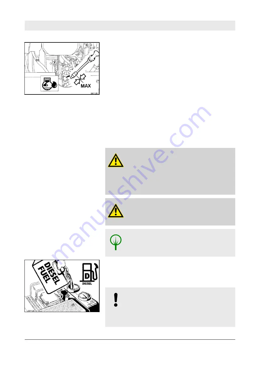
 Fig.  44 out, wipe it off with a lint-free,

clean cloth and reinsert it until it bottoms.

Pull out the oil dipstick again and read the oil level.

The oil level should reach the upper mark on the dipstick. If

the oil level is too low top up oil immediately.

After a running time of approx. one minute shut the engine

down, wait until all oil has run back into the oil sump, check

the oil level.

6.6.3  Check the fuel level

WARNING!
Fire hazard!

When working on the fuel system do not use open

fire, do not smoke, do not spill any fuel.

Do not refuel in closed rooms.

Shut down the engine.

WARNING!
Health hazard!

Do not inhale any fuel fumes.

ENVIRONMENT!

Catch running out fuel, do not let it seep into the

ground.

Clean the area around the filler opening.

Open the filler cap on the fuel tank and check the fuel level

visually.

NOTICE!

Contaminated fuel can cause malfunction or even

damage of the engine.

For quality and quantity of fuel refer to the "table of

fuels and lubricants".

Fig.  44

Fig.  45

Maintenance – Daily maintenance


BPR 70/70 D


57

Go to

Discount-Equipment.com 

to

order your parts

Summary of Contents for Bomag BPR 70/70 D

Page 1: ... plate Operating Instruction Maintenance Instruction Original Operating Instructions S N 101 692 75 1001 09 2016 008 200 14 EN www discount equipment com G o t o D i s c o u n t E q u i p m e n t c o m t o o r d e r y o u r p a r t s ...

Page 2: ...ne needs We sell worldwide for the brands Genie Terex JLG MultiQuip Mikasa Essick Whiteman Mayco Toro Stone Diamond Products Generac Magnum Airman Haulotte Barreto Power Blanket Nifty Lift Atlas Copco Chicago Pneumatic Allmand Miller Curber Skyjack Lull Skytrak Tsurumi Husquvarna Target Stow Wacker Sakai Mi T M Sullair Basic Dynapac MBW Weber Bartell Bennar Newman Haulotte Ditch Runner Menegotti M...

Page 3: ...ion 43 5 10 Stopping the vibratory plate shutting down the engine 44 5 11 Loading transport 45 6 Maintenance 47 6 1 General notes on maintenance 48 6 2 Fuels and lubricants 50 6 3 Table of fuels and lubricants 52 6 4 Running in instructions 53 6 5 Maintenance table 54 6 6 Daily maintenance 56 6 6 1 Clean the machine 56 6 6 2 Check the engine oil level 56 6 6 3 Check the fuel level 57 6 6 4 Check t...

Page 4: ...years 71 6 10 1 Change hydraulic oil and filter 71 6 11 As required 74 6 11 1 Check clean the air filter replace if necessary 74 6 11 2 Tightening the screws 75 6 11 3 Engine conservation 76 7 Trouble shooting 77 7 1 General notes 78 7 2 Starting with jump wires 79 7 3 Fuses 80 7 4 Engine problems 81 7 5 Trouble shooting Economizer 84 8 Disposal 85 8 1 Final shut down of machine 86 Table of conten...

Page 5: ...1 Introduction Introduction BPR 70 70 D 5 G o t o D i s c o u n t E q u i p m e n t c o m t o o r d e r y o u r p a r t s ...

Page 6: ...efore every start up carry out all required visual inspections and function tests Ensure the compliance with the specified operating maintenance and repair measures to maintain the functional safety of your machine A description of all necessary maintenance work maintenance intervals as well as information on fuels and lubricants can be found in the chapter Maintenance Do not service or repair you...

Page 7: ...notes do not constitute an extension of the warranty and liability conditions specified in the general sales and delivery conditions of BOMAG GmbH We wish you successful work with your BOMAG machine Introduction Foreword BPR 70 70 D 7 G o t o D i s c o u n t E q u i p m e n t c o m t o o r d e r y o u r p a r t s ...

Page 8: ...1 Serial number 2 Please enter here Engine type 1 Engine number 2 Fig 1 Machine type plate example Fig 2 Engine type plate example Introduction Machine type plate and engine type plate BPR 70 70 D 8 G o t o D i s c o u n t E q u i p m e n t c o m t o o r d e r y o u r p a r t s ...

Page 9: ...2 Technical data Technical data BPR 70 70 D 9 G o t o D i s c o u n t E q u i p m e n t c o m t o o r d e r y o u r p a r t s ...

Page 10: ...ECE W1 575 kg 1268 lbs Operating weight CECE W2 591 kg 1303 lbs Basic weight 570 kg 1257 lbs Economizer Optional equipment 5 kg 11 lbs Safety crank handle Optional equipment 3 kg 7 lbs Travel characteristics Working speed max 28 m min 92 ft min Max gradability depending on soil 35 35 Drive Engine manufacturer Hatz Hatz Technical data BPR 70 70 D 10 G o t o D i s c o u n t E q u i p m e n t c o m t...

Page 11: ...ere determined in accord ance with the following guidelines under equipment specific condi tions and by using harmonized standards n EC Machine Directive edition 2006 42 EC n Noise Emission Directive 2000 14 EC Noise Protection Direc tive 2003 10 EC n Vibration Protection Directive 2002 44 EC During operation these values may vary because of the prevailing operating conditions 2 1 1 Noise data LpA...

Page 12: ...ation in three orthog onal directions Total vibration value ahv 4 5 m s2 on crushed rock determined acc to ISO 5349 and EN 500 Associated uncertainty K 0 5 m s2 determined acc to EN 12096 Observe the daily vibration load work safety acc to 2002 44 EC Guaranteed sound power level Hand arm vibration Technical data Noise and vibration data BPR 70 70 D 12 G o t o D i s c o u n t E q u i p m e n t c o ...

Page 13: ...3 Safety regulations Safety regulations BPR 70 70 D 13 G o t o D i s c o u n t E q u i p m e n t c o m t o o r d e r y o u r p a r t s ...

Page 14: ...of handling work Should the recommendations in these instructions be different from the regulations valid in your country you must comply with the safety regulations valid in your country This machine must only be used for n Compaction of all types of soils n Repair work on all types of soil n Paving of walkways n Work in trenches n Underfilling and compaction of hard shoulders Dangers may arise f...

Page 15: ... machine the responsibilities must be clearly specified and complied with Persons under the influence of alcohol medicine or drugs are not allowed to operate service or repair the machine Maintenance and repair work requires specific knowledge and must therefore only be performed by trained specialists Unauthorized changes to the machine are prohibited for safety rea sons Original parts and access...

Page 16: ...ee operating weight in chapter Technical Data Loads must only be attached and hoisted by an expert capable person Fasten the lifting gear only at the specified lifting points Check lifting eye for damage before use Do not use a damaged or in any other way impaired lifting eye Do not lift or lower the machine jerkily The tension must always be effective in vertical direction The machine must not sw...

Page 17: ...d rooms and trenches Operate the machine only with the steering rod folded down Guide the machine only by the steering rod Guide the machine so hat your hands do not hit against solid objects danger of injury As a measure to avoid injury the machine must only be guided from the side by the steering handle Always keep an eye on a running machine Watch out for unusual noises and development of smoke...

Page 18: ... the setting of pressure relief valves Drain the hydraulic oil at operating temperature danger of scalding Any hydraulic oil must be caught and disposed of in an environ mentally friendly manner Always catch and dispose of hydraulic oils separately Do not start the engine after draining the hydraulic oil Once all work is completed with the system still depressurized check all connections and fitti...

Page 19: ...or clothes When injured by acid flush off with clear water and seek medical advice Metal objects e g tools rings watch straps must not come in contact with the battery poles danger of short circuit and burning For recharging remove the plugs from the battery to avoid the accumulation of highly explosive gases Observe the applicable instructions when starting with an auxiliary battery Switch off th...

Page 20: ...ways ensure an adequate supply of fresh air when starting in closed rooms Mark defective machines by attaching a warning note to the steering handle Welding Before starting welding work on the machine disconnect the battery and cover the fuel tank with insulating material Keep safety stickers in good condition and legible and follow their meaning Replace damaged and illegible safety stickers Repai...

Page 21: ...ce sticker 5 Operation sticker Throttle lever 6 Information sticker Guaranteed sound capacity level 7 Instruction sticker Wear ear defenders 8 Operation sticker Travel lever 9 Brief operating instructions 10 Information sticker Hydraulic oil Safety regulations BPR 70 70 D 21 G o t o D i s c o u n t E q u i p m e n t c o m t o o r d e r y o u r p a r t s ...

Page 22: ...Safety regulations BPR 70 70 D 22 G o t o D i s c o u n t E q u i p m e n t c o m t o o r d e r y o u r p a r t s ...

Page 23: ...4 Display and control elements Display and control elements BPR 70 70 D 23 G o t o D i s c o u n t E q u i p m e n t c o m t o o r d e r y o u r p a r t s ...

Page 24: ...on thoroughly before starting any operation on the machine Here all functions are described in detail The section Operation contains only brief descriptions of the indi vidual control steps Display and control elements General notes BPR 70 70 D 24 G o t o D i s c o u n t E q u i p m e n t c o m t o o r d e r y o u r p a r t s ...

Page 25: ...lever 4 Handle 5 Travel lever tip switch 6 Backup protection n Decompression lever n Safety crank handleOptional equipment Fig 5 Fig 6 Fig 7 Fig 8 Display and control elements Description of indicators and control elements BPR 70 70 D 25 G o t o D i s c o u n t E q u i p m e n t c o m t o o r d e r y o u r p a r t s ...

Page 26: ...n Position II Engine starts warning buzzer off n Operating hour meter n Economizer displayOptional equipment Fig 9 Fig 10 Fig 11 Display and control elements Description of indicators and control elements BPR 70 70 D 26 G o t o D i s c o u n t E q u i p m e n t c o m t o o r d e r y o u r p a r t s ...

Page 27: ...sed by the evaluation unit In order to achieve the required soil stiffness measured in MN m2 a reference measurement e g dynamic load plate must be made before the material is compacted This is necessary to find out how many LEDs in the Economizer display correspond with the required value in MN m2 on the soil being compacted The yellow LEDs represent the measuring value from the compac tion contr...

Page 28: ...sh Vibrating plates of the same type show identical measuring values when used on the same soil The measuring values achieved with different vibratory plates with Economizer from BOMAG can be made comparable by calibration to a reference value Display and control elements Function of the Economizer BPR 70 70 D 28 G o t o D i s c o u n t E q u i p m e n t c o m t o o r d e r y o u r p a r t s ...

Page 29: ...5 Operation Operation BPR 70 70 D 29 G o t o D i s c o u n t E q u i p m e n t c o m t o o r d e r y o u r p a r t s ...

Page 30: ...this machine you should thoroughly read chapter Indicators and control elements before starting work All indicators and control elements are described in detail in this chapter Operation General BPR 70 70 D 30 G o t o D i s c o u n t E q u i p m e n t c o m t o o r d e r y o u r p a r t s ...

Page 31: ...achine Check condition of engine and machine fuel tank and fuel lines for leaks hydraulic oil tank and lines for leaks screw connections for tight fit For a description of the following tasks refer to the chapter Daily maintenance Check the engine oil level top up if necessary Check the fuel level top up if necessary Check the hydraulic oil level top up if necessary Air filter service indicator Op...

Page 32: ...nd lower the steering rod so that it can swing freely Adjust the steering rod with the height adjustment 1 to the height of your body Fig 14 Operation Folding down the steering rod BPR 70 70 D 32 G o t o D i s c o u n t E q u i p m e n t c o m t o o r d e r y o u r p a r t s ...

Page 33: ...shut off valve must be opened manually Always perform the following work if n after the low oil level safety device has responded and engine oil has been filled up n if the fuel tank was driven empty n if the fuel in the supply line has been used up when cranking the engine free during cold starting or by starting faults Fill in fuel Press the hand lever Ä Fig 15 for approx five seconds against th...

Page 34: ...o per sons in the danger area of engine or machine and that all safety installations are in place Always hold on to the machine Always keep an eye on a running machine WARNING Loss of hearing Wear your personal noise protection means ear defenders before starting operation Set the throttle lever to position MAX Fig 16 Operation Start the engine BPR 70 70 D 34 G o t o D i s c o u n t E q u i p m e ...

Page 35: ...g buzzer sounds Turn the ignition key further to position II ð The engine starts As soon as the engine runs return the ignition key to position I ð The warning buzzer stops After starting take the throttle lever back to position MIN Run the engine warm for approx 1 to 2 minutes in idle speed Operation of the vibratory plate can be started as soon as the engine responds to short throttle com mands ...

Page 36: ... position I the battery is being charged when the engine is running as long as the battery voltage is at least 9 Volt Pull the decompression lever in direction of arrow to the end stop ð The compression lever clicks noticeably into place Set the throttle lever to position MAX Fig 19 Fig 20 Fig 21 Operation Emergency starting with safety crank handle BPR 70 70 D 36 G o t o D i s c o u n t E q u i p...

Page 37: ...ful turning and should by no means be interrupted during the starting process When the decompression lever returns to ini tial position after five revolutions the highest speed must be reached If the engine does not start repeat the starting process In case of incorrect operation and repeated starting the decompression lever must always be returned to initial position Hook the safety crank handle ...

Page 38: ...r a short while before starting work Operation of the vibratory plate can be started as soon as the engine responds to short throttle commands Fig 25 Operation Emergency starting with safety crank handle BPR 70 70 D 38 G o t o D i s c o u n t E q u i p m e n t c o m t o o r d e r y o u r p a r t s ...

Page 39: ...play value is higher during the first pass than during the second pass Due to the front rounded shape the contact area increases on loose material a slightly higher measuring value may be displayed n The Economizer does not reach the maximum display value even after many passes Due to different soil stiffness values the maximum value cannot be reached in each case n The display varies during a pas...

Page 40: ...also be located under the layer to be compacted and thus adversely affect compaction of the layers above In unfavour able cases an excessively varying material composition or moisture can influence the measuring results Check the sensor on the base plate for tight fit Both screws must be tight n Influence of the water content in the soil on the Economizer Display of reduced measuring values in cas...

Page 41: ...ever to position MIN this avoids prema ture wear of the centrifugal clutch Set the throttle lever to position MAX Press the upper part of the travel lever tip switch until the vibratory plate has reached the desired forward travel speed ð The machines vibrates forward with the adjusted speed Release the travel lever tip switch ð The travel lever tip switch returns to middle position The chosen for...

Page 42: ...ð The travel lever tip switch returns to middle position The chosen backwards speed is maintained Operate the travel lever tip switch until the vibratory plate vibrates on the spot Set the throttle lever Ä Fig 32 to position MIN Guide the vibratory plate by the steering rod in accordance the travel lever position until it is free again Drive backwards Fig 30 Vibration on the spot Fig 31 If the vib...

Page 43: ...hine must only be guided from the side by the steering handle Operation of the backup protection Ä Fig 33 changes the travel lever tip switch from reverse to forward travel Fig 33 Operation Backup protection BPR 70 70 D 43 G o t o D i s c o u n t E q u i p m e n t c o m t o o r d e r y o u r p a r t s ...

Page 44: ...ft the throttle lever to position MIN and let the engine run with idle speed for a short while ð Vibration is shut down Set the throttle lever to position STOP ð The warning buzzer sounds Turn the ignition key to position 0 and pull it out ð The warning buzzer no longer sounds Fig 34 Fig 35 Fig 36 Fig 37 Operation Stopping the vibratory plate shutting down the engine BPR 70 70 D 44 G o t o D i s c...

Page 45: ...Check lifting eye for damage before use Do not use a damaged or in any other way impaired lifting eye Do not lift or lower the machine jerkily The tension must always be effective in vertical direction The machine must not swing about when being lifted Do not step or stand under suspended loads Always use suitable lashing gear on the lifting points to lash down the machine Lash the machine down so...

Page 46: ... transport vehicle Lash the vibratory plate down to the transport vehicle so that it is secured against rolling sliding and turning over Fasten the lashing tackle at the marked lashing points Fig 39 Fig 40 Operation Loading transport BPR 70 70 D 46 G o t o D i s c o u n t E q u i p m e n t c o m t o o r d e r y o u r p a r t s ...

Page 47: ...6 Maintenance Maintenance BPR 70 70 D 47 G o t o D i s c o u n t E q u i p m e n t c o m t o o r d e r y o u r p a r t s ...

Page 48: ...erform maintenance work only with the engine shut down ENVIRONMENT During maintenance work catch all oils and fuels and do not let them seep into the ground or into the sewage system Dispose of oils and fuels envi ronmentally Keep used filters in a separate waste container and dispose of environmentally Open the hood to perform maintenance work Loosen the hood fasteners 1 on both sides and remove ...

Page 49: ...ntities are thoroughly adapted to each other and determine power tem perature level and exhaust gas quality of the engine If your engine has to work permanently in thin air at higher alti tudes and under full load you should consult our customer service or the customer service of the engine manufacturer Operating errors Incorrect inadequate maintenance If you cannot locate the cause of a fault or ...

Page 50: ... ensure strict cleanliness when filling in The fuel provision should always be topped up in due time so that the tank will not run dry The following fuel specifications are permitted n EN 590 n BS 2869 A1 and A2 n ASTM D 975 1 D and 2 D For engines used in EPA areas the use of fuels with a ultra low sulphur content is mandatory United States Environmental Protection Agency Winter fuel For winter o...

Page 51: ...Maintenance Fuels and lubricants BPR 70 70 D 51 G o t o D i s c o u n t E q u i p m e n t c o m t o o r d e r y o u r p a r t s ...

Page 52: ...F to 113 F SAE 10W 40 0 C to 40 C 32 F to 104 F SAE 30 15 C to 30 C 59 F to 86 F SAE 10W 5 C to 5 C 23 F to 41 F SAE 40 20 C to 35 C 68 F to 95 F Fuel Diesel Winter diesel fuel 12 C 10 4 F approx 10 0 l 2 6 gal us Vibrator shaft housing as engine oil approx 0 6 l 0 16 gal us Hydraulic system Hydraulic oil ISO HV32 kinem viscosity of 32 mm2 s at 40 C 104 F approx 2 6 l 0 7 gal us Maintenance Table ...

Page 53: ...he normal level after approx 100 to 200 operating hours After 25 operating hours Change the engine oil Check engine and machine for leaks Check the valve clearance adjust if necessary Retighten the fastening screws on air filter exhaust fuel tank and other attachments Retighten the bolted connections on the machine Check the vibration drive V belts Check the oil level in the vibrator housing Maint...

Page 54: ...ust the valve clearance X 6 8 3 Check the oil level in the exciter housing X 6 9 1 Change engine oil and oil filter at least every 250 operating hours X 6 9 2 Replace the fuel filter X 6 9 3 Change the oil in the exciter housing at least every 500 operating hours X 6 9 4 Check the rubber buffers X 6 9 5 Check the V belt tension if necessary replace the V belt X 6 10 1 Change hydraulic oil and filt...

Page 55: ...Maintenance Maintenance table BPR 70 70 D 55 G o t o D i s c o u n t E q u i p m e n t c o m t o o r d e r y o u r p a r t s ...

Page 56: ...ake and subsequently clean the cooling fins NOTICE Do not guide the water jet directly into the dry air filter intake opening Ä Fig 43 and into the opening for the crank handle Cover the electric equipment against the direct water jet After wet cleaning run the engine warm to evaporate all water residues and to avoid corrosion 6 6 2 Check the engine oil level NOTICE Park the machine on level groun...

Page 57: ...RNING Fire hazard When working on the fuel system do not use open fire do not smoke do not spill any fuel Do not refuel in closed rooms Shut down the engine WARNING Health hazard Do not inhale any fuel fumes ENVIRONMENT Catch running out fuel do not let it seep into the ground Clean the area around the filler opening Open the filler cap on the fuel tank and check the fuel level visually NOTICE Con...

Page 58: ...dropped check all lines hoses and components for leaks Check the oil level in the inspection glass Ä Fig 46 At room temperature of approx 20 C 68 F the hydraulic oil level should reach approx the middle of the inspection glass Minimum level 1 3 of inspection glass For quality of oil refer to the table of fuels and lubricants Top up hydraulioc oil if necessary 6 6 5 Check the air filter service ind...

Page 59: ...ng the air filter Under very dusty conditions check the rubber bel lows several times every day 6 6 6 Check the rubber buffers Check all rubber buffers Ä Fig 48 for tight fit cracks and damage and replace immediately if damaged Fig 47 Fig 48 Maintenance Daily maintenance BPR 70 70 D 59 G o t o D i s c o u n t E q u i p m e n t c o m t o o r d e r y o u r p a r t s ...

Page 60: ...Fig 49 from all cooling fins and cooling air intake openings and blow it off with compressed air WARNING Fire hazard Do not use any inflammable solvents NOTICE Do not guide the water jet directly into the cooling air openings of the recoil starter into the air filter and on electrical equipment On a oil contaminated engine use a cold cleansing agent for cleaning After a sufficient soaking time cle...

Page 61: ... tank should contain only a little quantity of fuel Unscrew the drain plug Ä Fig 50 underneath the fuel tank drain off fuel and catch it Once all fuel has run out screw the oil drain plug back in with a new seal ring After the tank has been driven empty the mechan ical oil pressure monitoring system must be acti vated see chapter Actuating the oil pressure monitoring system Fig 50 Maintenance Main...

Page 62: ... not need to be checked Each battery suffers under self discharge which may in not checked occa sionally even cause damage to the battery as a result of exhaustive discharge The following therefore applies for the service life Switch off all consumers e g ignition Check open circuit voltage of the battery at regular intervals At least once per month Reference values 12 6 V fully charged 12 3 V 50 ...

Page 63: ...an battery poles and pole clamps and grease them with pole grease Vaseline Check the condition of the vibration insulation mats replace if necessary On serviceable batteries check the acid level if necessary top up to the filling mark with distilled water Install battery and vibration insulation mats Fasten the bracket again Close the hood 6 8 2 Check adjust the valve clearance NOTICE We recommend...

Page 64: ...an be felt Unscrew cylinder head cover Ä Fig 53 and take off with gasket Generally replace the gasket Check the valve clearance between rocker arm and valve stem with a feeler gauge Ä Fig 54 on both valves Check the valve clearance Fig 52 Fig 53 Fig 54 Maintenance Maintenance every 6 months BPR 70 70 D 64 G o t o D i s c o u n t E q u i p m e n t c o m t o o r d e r y o u r p a r t s ...

Page 65: ... the area around breather and drain plug Unscrew the bleeding screw 1 Ä Fig 56 Unscrew the oil level inspection plug 2 and check the oil level The oil level must reach the bottom edge of the inspection opening if necessary fill in oil For quality of oil refer to the table of fuels and lubricants Clean the oil level inspection plug and screw in with sealing agent e g BOMAG 009 700 16 Screw the blee...

Page 66: ...ning out oil and dispose of environmen tally together with the oil filter Park the machine on level ground so that the engine is in horizontal position Pull out the oil dipstick Ä Fig 57 Clean the drain hose from dust and dirt Unscrew the oil drain plug Ä Fig 58 and catch any oil run ning out Clean the drain plug and screw it back in tightening torque 20 Nm 14 8 ft lbs Fig 57 Fig 58 Maintenance An...

Page 67: ...the filler opening Ä Fig 60 Push the dipstick back in After a short test run check for leaks Check the oil level on the dipstick Ä Fig 61 correct if nec essary 6 9 2 Replacing the fuel filter WARNING Fire hazard When working on the fuel system do not use open fire do not smoke do not spill any fuel Fig 59 Fig 60 Fig 61 Maintenance Annual maintenance BPR 70 70 D 67 G o t o D i s c o u n t E q u i p...

Page 68: ...lush out with clean diesel fuel Install the new fuel filter by observing the flow direction Fill the fuel tank again After the tank has been driven empty the mechan ical oil pressure monitoring system must be acti vated see chapter Actuating the oil pressure monitoring system 6 9 3 Changing the oil in the exciter housing NOTICE Park the machine on level ground For quality and quantity of oil refer...

Page 69: ...upport it safely Tilt the machine to the opposite side and secure it properly Fill in fresh oil through the level inspection opening Ä Fig 64 Stand the machine on level ground and check the oil level Ä Fig 65 The oil level must reach the bottom edge of the oil level inspection bore Clean level plug 2 and screw in with sealing agent e g BOMAG 009 700 16 Screw vent plug 1 tightly back in Fig 63 Fig ...

Page 70: ...n measure ment is exceeded Remove the safety cover 1 Ä Fig 68 Disassemble the front V belt pulley 2 Take off the V belt and replace it with a new one Attach the spacer 3 Assemble the front V belt pulley and fasten it Assemble the guard and fasten it with screws Tightening torque 15 Nm 11 ft lbs Install the top V belt guard Checking the V belt Fig 66 Fig 67 Replacing the V belt Fig 68 Maintenance A...

Page 71: ...ity and quantity of oil refer to the table of fuels and lubricants ENVIRONMENT Catch running out oil and dispose of environmen tally together with the filter Open the hood Clean hydraulic tank and surrounding area Unscrew the plug 1 Ä Fig 69 Take out the breather filter 3 Replace and insert the breather filter with seal ring 2 Replace the plug and screw it in tightly Changing the breather filter F...

Page 72: ...n Replace the hydraulic oil filter 2 and the seal ring 1 and fasten it to the connecting flange Assemble the connecting flange 4 with the new seal ring 3 to the hydraulic oil tank tightening torque 13 Nm 9 6 ft lbs Change hydraulic oil and filter Fig 70 Fig 71 Fig 72 Fig 73 Maintenance Maintenance every 2 years BPR 70 70 D 72 G o t o D i s c o u n t E q u i p m e n t c o m t o o r d e r y o u r p ...

Page 73: ...p up if necessary ð Nominal value Middle of inspection glass Assemble connecting sockets and hoses Close the hood Fig 74 Fig 75 Maintenance Maintenance every 2 years BPR 70 70 D 73 G o t o D i s c o u n t E q u i p m e n t c o m t o o r d e r y o u r p a r t s ...

Page 74: ...ective because of damage e g cracks and cause damage to the engine In case of wet or oily dirt replace the filter element Unscrew the wing nut for cover 1 Ä Fig 76 and take off the cover Pull out the air filter WARNING Danger of injury Always wear protective clothes goggles gloves when working with compressed air Blow the air filter out from inside to outside with dry com pressed air max 5 bar 72 ...

Page 75: ...n unscrewed Strength classes for screws with untreated non lubricated sur faces The quality designations are stamped on the screw heads 8 8 8 G 10 9 10 K 12 9 12 K The values result in a 90 utilization of the screw s yielding point at a coefficient of friction of μ total 0 14 The compliance with the tightening torques is to be checked with torque wrenches The tightening torques are not applicable ...

Page 76: ...ts Take the cylinder head cover off spray the rocker chamber with a mixture of diesel fuel and 10 anti corrosion oil Then fasten the cover again Crank the engine several times to spray the combustion chamber throttle lever in stop position Take the V belt off and spray the grooves of the V belt pulleys with anti corrosion oil Remove the anti corrosion oil before taking the machine back into servic...

Page 77: ...7 Trouble shooting Trouble shooting BPR 70 70 D 77 G o t o D i s c o u n t E q u i p m e n t c o m t o o r d e r y o u r p a r t s ...

Page 78: ...nsufficient maintenance Whenever a fault occurs you should therefore thoroughly read these instruction on correct oper ation and maintenance If you cannot locate the cause of a fault or rectify it yourself by fol lowing the trouble shooting chart you should contact our customer service department Trouble shooting General notes BPR 70 70 D 78 G o t o D i s c o u n t E q u i p m e n t c o m t o o r ...

Page 79: ...and screw connec tions replace if necessary Join the plus poles on external battery and starter battery with the jump wire Ä Fig 82 Use the second jump start cable to connect the negative poles on external battery and starter battery Start the engine as described in the chapter Starting the engine When the engine is running remove the jump start cable from the two negative poles first and from the...

Page 80: ...uses NOTICE Always cover the fuse with the protective cover Fuse 25 A Ä Fig 83 NOTICE Machines with Economizer are protected by an additional fuse 5 A Optional equipment Fig 83 Trouble shooting Fuses BPR 70 70 D 80 G o t o D i s c o u n t E q u i p m e n t c o m t o o r d e r y o u r p a r t s ...

Page 81: ...perature below starting limit Observe cold start instructions Fuel gelled because of insufficient cold compati bility Pull the fuel hose off the fuel lift pump and check whether fuel runs out of the fuel pump clear and without gel In case of gelled fuel you should either warm the engine up or drain the complete fuel supply system Fill with a temperature resistant fuel mix ture Starter speed too lo...

Page 82: ...the our cus tomer service Engine ignites but does not continue to run when switching the starter motor off Fuel filter clogged Replace the fuel filter Fuel supply interrupted Check the entire fuel system system atically Stop signal from monitoring elements connected with the oil pressure monitoring facility Check the oil level no oil pressure Check the oil level Engine shuts down by itself during ...

Page 83: ...k exhaust smoke Air filter dirty Clean or replace the air filter Incorrect valve clearance Adjust the valve clearance Injection nozzle out of order Have examined by a specialist Engine overheating Too much oil in engine Drain the engine oil down to the top mark on the dipstick Insufficient cooling Clean the cooling air area Dirt in the entire area of the cooling air flow Clean the cooling air area...

Page 84: ...defective Sensor cable defective Status LED flashing Frequency detected but outside permissible range Engine speed too low Vibration frequency too low Sensor defective atypical soil V belt slipping incorrect V belt installed Trouble shooting Trouble shooting Economizer BPR 70 70 D 84 G o t o D i s c o u n t E q u i p m e n t c o m t o o r d e r y o u r p a r t s ...

Page 85: ...8 Disposal Disposal BPR 70 70 D 85 G o t o D i s c o u n t E q u i p m e n t c o m t o o r d e r y o u r p a r t s ...

Page 86: ...ith skin or clothes Wear protective clothing Remove the batteries and dispose of in compliance with legal regulations ENVIRONMENT Collect all fuels and lubricants do not let them seep into the ground and dispose of in compliance with legal regulations Empty the fuel tank Drain lubrication oil from engine and exciter housing Drain off hydraulic oil WARNING Danger of explosion Parts that previously ...

Page 87: ...ne needs We sell worldwide for the brands Genie Terex JLG MultiQuip Mikasa Essick Whiteman Mayco Toro Stone Diamond Products Generac Magnum Airman Haulotte Barreto Power Blanket Nifty Lift Atlas Copco Chicago Pneumatic Allmand Miller Curber Skyjack Lull Skytrak Tsurumi Husquvarna Target Stow Wacker Sakai Mi T M Sullair Basic Dynapac MBW Weber Bartell Bennar Newman Haulotte Ditch Runner Menegotti M...

Reviews: