FATEK P5 Series Connection Manual Download Page 179

179 


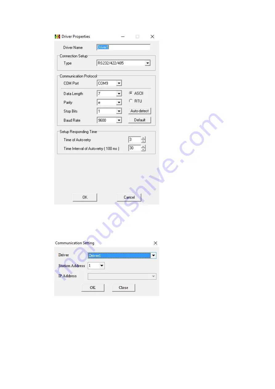
In ISPSoft, under the Tools menu option, select Communication Settings. Select the 

name of the connection configured in COMMGR and press OK. 


Under the PLC menu option, select Transfer and Upload. If there is a program on the 

PLC, it will be uploaded and the system settings can be configured. If there is no 

program present on the PLC one will have to be downloaded.   

Summary of Contents for P5 Series

Page 1: ...1 P5Series ...

Page 2: ...0 14 May 24 2016 Add YASKAWA Extended MEMOBUS V1 0 15 Jun 20 2016 Add Keyence KV 3000 5000 5500 7500 ethernet and KV L21V 3000 5000 5500 V1 0 16 Jul 6 2016 Add Allen Bradley SLC and MicroLogix Series V1 0 16 Jul 15 2016 Update KV Nano host link V1 0 17 Nov 25 2016 Add QSeries Serial Communication Q L Series ENET and Update FBe PLC setting V1 0 17 Nov 29 2016 Add Omron SYSMAC CP Series Ethernet and...

Page 3: ...Port 77 2 2 10 Q L Series ENET 82 2 3 Omron 86 2 3 1 Omron SYSMAC CP Series 86 2 3 2 Omron SYSMAC CP Series Ethernet 91 2 3 3 Omron SYSMAC CS CJ Series 94 2 3 4 Omron SYSMAC CS CJ Series Ethernet 98 2 3 5 Omron SYSMAC CPM Series 103 2 4 Siemens 107 2 4 1 Siemens S7 200 SMART 107 2 4 2 Siemens S7 200 SMART Ethernet 113 2 4 3 Siemens S7 1200 Ethernet 118 2 4 4 Siemens S7 200 122 2 4 5 Siemens LOGO 1...

Page 4: ... 188 2 11 YASKAWA 190 2 11 1 Extended MEMOBUS 190 2 11 2 MP Series Extension Ethernet 193 2 12 Keyence 196 2 12 1 KV 3000 5000 5500 7500 Ethernet 196 2 12 2 KV L21V 3000 5000 5500 host link 201 2 12 3 KV Nano host link 210 2 13 Beckhoff Automation 214 2 13 1 Twincat Ethernet 214 2 14 Koyo 218 2 14 1 Direct 218 1 HMI Model Serial Information P5043S P5043N P5070VS P5102VS Serial Interface COM1 RS 23...

Page 5: ... 7 DATA 8 DATA 9 RX P5070S P5070N P5070N1 P5102S P5102N P5102N1 Serial Interface COM1 RS 232 TXD RXD RTS CTS COM3 RS 422 485 COM4 RS 485 Serial Layout RS 232 PIN COM1 1 2 RX 3 TX 4 5 GND 6 7 RTS 8 CTS 9 RS 422 485 Old Model PIN COM3 RS 422 COM3 RS 485 COM4 ...

Page 6: ...85 COM4 1 DATA 2 DATA 3 ISO_GND ISO_GND ISO_GND 4 RX 5 RX 6 TX DATA 7 TX DATA 2 PLC Connection 2 1 FATEK Automation Corp FBs B1 B1z HB1 2 1 1 1 Communication Setting Item Default Setting Remark Signal Level RS232 Baud Rate 9600 Data Length 7 Stop Bit 1 Parity Even PLC Station No 1 Must match PLC ...

Page 7: ...ay WS 16 DDDD 0 999 Step Relay RT 16 DDDD 0 255 Timer Register RC 16 DDDD 0 199 Counter Register DRC 32 DDDD 200 255 Counter Register R 16 DDDD 0 8071 Data Register D 16 DDDD 0 4095 Data Register F 16 DDDD 0 8191 File Register 2 1 1 3 Connecting to PLC Configuring the PLC Use the application WinProLadder ver 3 25 to configure the serial port of the PLC Connect the PLC to a computer In the applicat...

Page 8: ...LC tab select the Setting option and choose Port 0 Here the Baud rate and other parameters of the serial port can be configured Note For more detailed information please refer to the PLC manual Connecting PLC to HMI ...

Page 9: ...ial Under Manufacturer select FATEK Automation Corp Under Product Series select FATEK FBs B1 B1z HB1 Under Port select COM1 Verify the other parameters are consistent with the settings on the PLC 2 1 1 4 Wiring Diagrams HMI COM1 Pinout Looking into COM1 Port PIN COM1 RS232 1 2 RX 3 TX ...

Page 10: ...10 4 5 GND 6 7 RTS 8 CTS 9 PLC RS232 Pinout Looking into PLC PIN Signal 1 2 GND 3 TX 4 RX All P5 Series HMI COM1 PLC RS232 Port 2 RX 3 TX 3 TX 4 RX 5 GND 2 GND Wiring Diagrams All P5Series ...

Page 11: ... match PLC port setting Communication Method FATEK Communication Protocol 2 1 2 2 Memory Resource Review Device Data Bits Address Format Min Max Description X 1 DDDD 0 255 Input Discrete Y 1 DDDD 0 255 Output Relay M 1 DDDD 0 2001 Internal Relay S 1 DDDD 0 999 Step Relay T 1 DDDD 0 255 Timer Discrete C 1 DDDD 0 255 Counter Discrete WX 16 DDDD 0 255 Input Discrete ...

Page 12: ...ng the PLC Use the application WinProLadder ver 3 25 to configure the serial port of the PLC Connect the PLC to a computer In the application under the PLC tab select the On Line option In the dialog select RS232 for the Connection Name and press Edit Within the edit dialog select the port number the PLC is connected to Press OK to confirm the settings Under the PLC tab select the Setting option a...

Page 13: ...13 Note For more detailed information please refer to the PLC manual Connecting PLC to HMI Within the Link configuration window in FvDesigner ...

Page 14: ... PLC Verify the other parameters are consistent with the settings on the PLC 2 1 2 4 Wiring Diagrams Note The connections were made between the HMI and the FB DTBR E module The module provides ports for each connection type PLC RS232 Pinout Looking into port0 PLC RS485 Pinout PIN Port 0 RS 232 Port 2 RS 485 1 DATA 2 TXD DATA 3 RXD FG 4 5 GND 6 7 8 9 HMI COM1 Pinout Looking into COM1 Port ...

Page 15: ... 3 TX 4 5 GND 6 7 RTS 8 CTS 9 HMI COM3 Pinout Looking into HMI Device PIN COM3 RS 422 RS 485 1 2 3 ISO_GND 4 5 6 DATA 7 DATA All P5 Series HMI COM1 PLC RS232 Port 2 RX 2 TXD 3 TX 3 RXD 5 GND 5 GND Wiring Diagrams All P5Series ...

Page 16: ...N P5070N1 P5102S P5102N P5102N1 HMI COM3 PLC RS485 Port 6 DATA DATA 7 DATA DATA Wiring Diagrams P5070S P5070N P5070N1 P5102S P5102N P5102N1 P5043S P5043N P5070VS P5102VS HMI COM2 PLC RS485 Port 1 DATA DATA 6 DATA DATA ...

Page 17: ...1 3 Port 500 PLC Station No 0 Communication Method TCP 2 1 3 2 Memory Resource Review Device Data Bits Address Format Min Max Description X 1 DDDD 0 255 Input Discrete Y 1 DDDD 0 255 Output Relay M 1 DDDD 0 2001 Internal Relay S 1 DDDD 0 999 Step Relay T 1 DDDD 0 255 Timer Discrete C 1 DDDD 0 255 Counter Discrete WX 16 DDDD 0 255 Input Discrete WY 16 DDDD 0 255 Output Relay ...

Page 18: ...ess of the PLC Connect an Ethernet cable to the PLC Under Attached Media select LAN and press scan Select the PLC to connect to and right click or press Properties to change the IP Note The default IP address for the PLC has 1 for its third octet If the IP address of the computer has a different number at that position the PLC will not show up in the scan Configure network settings on the computer...

Page 19: ...lease refer to the PLC manual Connecting PLC to HMI Within the Link configuration window in FvDesigner Under Interface Type select Ethernet Under Manufacturer select FATEK Automation Corp Under Product Series select FATEK FBs B1 B1z HB1 TCP ...

Page 20: ...DD 0 999 Step Relay T 1 DDDD 0 255 Timer Discrete C 1 DDDD 0 255 Counter Discrete WX 16 DDDD 0 255 Input Discrete WY 16 DDDD 0 255 Output Relay WM 16 DDDD 0 2001 Input Relay WS 16 DDDD 0 999 Step Relay RT 16 DDDD 0 255 Timer Register RC 16 DDDD 0 199 Counter Register DRC 32 DDDD 200 255 Counter Register R 16 DDDD 0 8071 Data Register D 16 DDDD 0 4095 Data Register 2 1 4 3 Connecting to HMI Configu...

Page 21: ...ddress of the computer has a different number at that position the PLC will not show up in the scan Configure network settings on the computer to be able to see the PLC in the local network In the dialog window the IP address and other parameters of the PLC can be configured Note For more detailed information please refer to the PLC manual Connecting PLC to HMI ...

Page 22: ...Corp Under Product Series select FATEK FBe TCP Use the IP address assigned on the PLC Leave the Port at the default value FBs B1 B1z HB1 UDP 2 1 5 1 Communication Setting Item Default Settings Remark Signal Level Ethernet Internet Protocol 192 168 1 100 Port 500 PLC Station No 0 Communication Method UDP 2 1 5 2 Memory Resource Review ...

Page 23: ...DDDD 0 999 Step Relay RT 16 DDDD 0 255 Timer Register RC 16 DDDD 0 199 Counter Register DRC 32 DDDD 200 255 Counter Register R 16 DDDD 0 8071 Data Register D 16 DDDD 0 4095 Data Register F 16 DDDD 0 8191 File Register 2 1 5 3 Connecting to HMI Configuring IP Address on PLC Use the application FATEK Ethernet Module Configuration Tool to configure the IP address of the PLC Connect an Ethernet cable ...

Page 24: ...24 configured Note For more detailed information please refer to the PLC manual Connecting PLC to HMI ...

Page 25: ...indow in FvDesigner Under Interface Type select Ethernet Under Manufacturer select FATEK Automation Corp Under Product Series select FATEK FBe UDP Use the IP address assigned on the PLC Leave the Port at the default value 2 2 Mitsubishi ...

Page 26: ...Input Discrete 1 0 377 Y Output Relay 1 0 377 M Internal Relay 1 0 7999 SM Special Relay 1 8000 8255 S Step Relay 1 0 4095 TS Timer Discrete 1 0 255 CS Counter Discrete 1 0 255 WX Input Discrete 16 0 360 WY Output Relay 16 0 360 WM Internal Relay 16 0 7984 WS Step Relay 16 0 4080 TN Timer Memory 16 0 255 CN Counter Memory 16 0 199 D Data Register 16 0 7999 SD Special Data Register 16 8000 8255 DCN...

Page 27: ...terface Type select Serial Under Manufacturer select Mitsubishi Electric Corporation Under Product Series select Mitsubishi FX2N Under Port select COM3 2 2 1 4 Wiring Diagrams PLC RS422 Pinout View from soldering point of the cable PIN Signal 1 RX 2 RX 3 GND 4 TX ...

Page 28: ...nto HMI Device PIN COM3 RS 422 RS 485 1 2 3 ISO_GND 4 RX 5 RX 6 TX 7 TX P5070S P5070N P5070N1 P5102N P5102N1 HMI COM3 PLC RS422 Port 5 RX 4 TX 4 RX 7 TX 7 TX 1 RX 6 TX 2 RX 3 ISO_GND 3 GND Wiring Diagrams P5070S P5070N P5070N1 P5102N P5102N1 ...

Page 29: ...5043N P5070VS P5102VS HMI COM2 PLC RS422 Port 9 RX 4 TX 4 RX 7 TX 6 TX 1 RX 1 TX 2 RX 5 GND 3 GND Wiring Diagrams P5043S P5043N P5070VS P5102VS FX2N 485BD 2 2 2 1 Communication Setting Item Default Setting Remark ...

Page 30: ...l Relay 1 8000 8255 S Step Relay 1 0 999 TS Timer Discrete 1 0 255 CS Counter Discrete 1 0 199 WX Input Discrete 16 0 360 WY Output Relay 16 0 360 WM Internal Relay 16 0 3056 WS Step Relay 16 0 976 TN Timer Memory 16 0 255 CN Counter Memory 16 0 199 D Data Register 16 0 7999 SD Special Data Register 16 8000 8255 DCN Counter Memory 32 200 255 2 2 2 3 Connecting to HMI Configuring the PLC Use MELSOF...

Page 31: ...ect Serial USB in the Transfer Setup Communication window Select the RS 232C radio button and select the COM Port that the PLC is connected at Click Connection Test to verify the connection and then press OK ...

Page 32: ...32 After confirming the Parameter option is checked press Execute in the Online Data Operation window Under the Project Sidebar expand Parameter and select PLC Parameter ...

Page 33: ...33 Navigate to the PLC System 2 tab and configure it to the settings detailed below Check Operate Communication Setting to enable configuration Set Protocol to Dedicated Protocol Set Parity to Even ...

Page 34: ...signer Note For more detailed information please refer to the PLC manual Connecting PLC to HMI Within the Link configuration window in FvDesigner Under Interface Type select Serial Under Manufacturer select Mitsubishi Electric Corporation Under Product Series select Mitsubishi FX2N 485BD Under Port select COM3 2 2 2 4 Wiring Diagrams PLC RS422 Pinout ...

Page 35: ...o HMI Device PIN COM3 RS 422 RS 485 1 2 3 ISO_GND 4 RX 5 RX 6 TX 7 TX P5070S P5070N P5070N1 P5102N P5102N1 HMI COM3 PLC RS422 Port 5 RX SDB 4 RX SDA 7 TX RDB 6 TX RDA 3 ISO_GND SG Wiring Diagrams P5070S P5070N P5070N1 P5102N P5102N1 ...

Page 36: ...36 P5043S P5043N P5070VS P5102VS HMI COM2 PLC RS422 Port 9 RX SDB 4 RX SDA 6 TX RDB 1 TX RDA 5 GND SG Wiring Diagrams P5043S P5043N P5070VS P5102VS ...

Page 37: ...ta Length 7 Stop Bit 1 Parity Even PLC Station No 0 Communication Method Programming Protocol 2 2 3 2 Memory Resource Review Device Description Data bit Min Max X Input Discrete 1 0 377 Y Output Relay 1 0 377 M Internal Relay 1 0 7999 SM Special Relay 1 8000 8511 S Step Relay 1 0 4095 TS Timer Discrete 1 0 511 ...

Page 38: ... D Data Register 16 0 7999 SD Special Data Register 16 8000 8511 R Extended Register 16 0 32767 DCN Counter Memory 32 200 255 2 2 3 3 Connecting to HMI Connecting PLC to HMI Within the Link configuration window in FvDesigner Under Interface Type select Serial Under Manufacturer select Mitsubishi Electric Corporation Under Product Series select Mitsubishi FX3U 3G Under Port select COM3 ...

Page 39: ...C RS422 Pinout View from soldering point of the cable PIN Signal 1 RX 2 RX 3 GND 4 TX 5 6 7 TX 8 HMI COM3 Pinout Looking into HMI Device PIN COM3 RS 422 RS 485 1 2 3 ISO_GND 4 RX 5 RX 6 TX 7 TX P5070S P5070N P5070N1 P5102N P5102N1 ...

Page 40: ... TX 7 TX 1 RX 6 TX 2 RX 3 ISO_GND 3 GND Wiring Diagrams P5070S P5070N P5070N1 P5102N P5102N1 P5043S P5043N P5070VS P5102VS HMI COM2 PLC RS422 Port 9 RX 4 TX 4 RX 7 TX 6 TX 1 RX 1 TX 2 RX 5 GND 3 GND Wiring Diagrams P5043S P5043N P5070VS P5102VS ...

Page 41: ...rol Form1 Without CR LF Checksum Yes Communication Method Computer Link 2 2 4 2 Memory Resource Review Device Description Data bit Min Max X Input Discrete 1 0 377 Y Output Relay 1 0 377 M Internal Relay 1 0 7679 SM Special Relay 1 8000 8511 S Step Relay 1 0 4095 TS Timer Discrete 1 0 511 CS Counter Discrete 1 0 199 WX Input Discrete 16 0 360 WY Output Relay 16 0 360 ...

Page 42: ... Special Data Register 16 8000 8511 R Extended Register 16 0 32767 DCN Counter Memory 32 200 255 2 2 4 3 Connecting to HMI Configuring the PLC Use MELSOFT GX Works2 to configure the port of the PLC Under the Online menu option select Read from PLC Select the FXCPU PLC series Select Serial USB in the Transfer Setup Communication window ...

Page 43: ...io button and select the COM Port that the PLC is connected at Click Connection Test to verify the connection and then press OK After confirming the Parameter option is checked press Execute in the Online Data Operation window ...

Page 44: ...44 Under the Project Sidebar expand Parameter and select PLC Parameter Navigate to the PLC System 2 tab and configure it to the settings detailed below ...

Page 45: ...Dedicated Protocol Set Parity to Even Set Transmission Speed to 19200 Set H W Type to RS 485 Check the Sum Check checkbox Verify the Station Number is consistent with the one set in FvDesigner Note For more detailed information please refer to the PLC manual Connecting PLC to HMI ...

Page 46: ... in FvDesigner Under Interface Type select Serial Under Manufacturer select Mitsubishi Electric Corporation Under Product Series select Mitsubishi FX3U 3G 485BD Under Port select COM3 2 2 4 4 Wiring Diagrams PLC RS422 Pinout HMI COM3 Pinout ...

Page 47: ...vice PIN COM3 RS 422 RS 485 1 2 3 ISO_GND 4 RX 5 RX 6 TX 7 TX P5070S P5070N P5070N1 P5102N P5102N1 HMI COM3 PLC RS422 Port 5 RX SDB 4 RX SDA 7 TX RDB 6 TX RDA 3 ISO_GND SG Wiring Diagrams P5070S P5070N P5070N1 P5102N P5102N1 ...

Page 48: ... TX RDA 5 GND SG Wiring Diagrams P5043S P5043N P5070VS P5102VS FX3U Ethernet 2 2 5 1 Communication Setting Item Default Setting Remark Signal Level Ethernet Internet Protocol 0 0 0 0 Port 5001 PLC Station No 0 Communication Method MC protocol Binary ASCII 2 2 5 2 Memory Resource Review ...

Page 49: ...ernal Relay 16 0 7664 WS Step Relay 16 0 4080 TN Timer Memory 16 0 511 CN Counter Memory 16 0 199 D Data Register 16 0 7999 SD Special Data Register 16 8000 8511 R Extended Register 16 0 32767 DCN Counter Memory 32 200 255 2 2 5 3 Connecting to HMI Configuring IP Address on PLC Use MELSOFT GX Works2 to configure the IP address of the PLC Under the Online menu option select Read from PLC Select the...

Page 50: ...io button and select the COM Port that the PLC is connected at Click Connection Test to verify the connection and then press OK After confirming the Parameter option is checked press Execute in the Online Data Operation window ...

Page 51: ...51 Under the Project Sidebar expand Parameter and select PLC Parameter In the Ethernet Port tab set an open IP address ...

Page 52: ...ire Open System column to MC Protocol For the Host Station Port No set row 1 to 5001 row 2 to 5002 and so on Under the Online menu option select Write to PLC to save the settings to the PLC Press Execute in the Online Data Operation window ...

Page 53: ...53 Note For more detailed information please refer to the PLC manual Connecting PLC to HMI ...

Page 54: ...shi FX3U ENET ADP options The last part of the series name BINARY or ASCII should be consistent with the Connection Data Code set in the Ethernet Port for the PLC Enter the IP Address that was written into the PLC Enter 5001 for the Port FX5U Serial 2 2 6 1 Communication Setting Item Default Setting Remark Signal Level RS485 Baud Rate 19200 Data Length 8 Stop Bit 1 Parity None PLC Station No 0 ...

Page 55: ...023 SS Retentive Timer Contact 1 DDDD 0 1023 SC Retentive Timer Coil 1 DDDD 0 1023 CS Counter Contact 1 DDDD 0 1023 CC Counter Coil 1 DDDD 0 1023 LCS 1 Long Counter Contact 1 DDDD 0 1023 LCC 1 Long Counter Coil 1 DDDD 0 1023 SM Special Relay 1 DDDD 0 9999 WX 2 Input Relay 16 OOOO 0 1760 WY 2 Output Relay 16 OOOO 0 1760 WM 3 Internal Relay 16 DDDDD 0 32752 B_Word 3 Link Relay 16 HHHH 0 7FF0 F_Word ...

Page 56: ...7FFF SD Special Register 16 DDDDD 0 11999 R File Register 16 DDDDD 0 32767 Z Index Register 16 DD 0 23 LCN 1 Long Counter Current Value 32 DDDD 0 1023 LZ Long Index Register 32 DD 0 11 1 Binary mode support only 2 Address increased by 0 20 40 60 3 Address increased by 0 20 40 60 2 2 6 3 Connecting to HMI Configuring the PLC Connect the PLC using an Ethernet cable The following setup uses an Ethern...

Page 57: ...57 In the connection window select Ethernet Board Click PLC Module and in the dialog window select the Ethernet Port Direct Connection radio button ...

Page 58: ...58 Click Connection Test to verify the connection and then press OK Click Select All in the Online Data Operation window and press Execute Allow the read to finish ...

Page 59: ...U and Module Parameter and select 485 Serial Port Under Basic Settings change Communication Protocol Type to MC Protocol Under Fixed Setting change Message Pattern to Pattern 1 and verify the station number is consistent with the one set in FvDesigner ...

Page 60: ...eration window Note For more detailed information please refer to the PLC manual Connecting PLC to HMI Within the Link configuration window in FvDesigner Under Interface Type select Serial Under Manufacturer select Mitsubishi Electric Corporation Under Product Series select Mitsubishi FX5U SERIAL Verify the parameters match the window above ...

Page 61: ...61 2 2 6 4 Wiring Diagrams PLC RS422 Pinout HMI COM3 Pinout Looking into HMI Device PIN COM3 RS 422 RS 485 1 ...

Page 62: ...N P5070N1 P5102N P5102N1 HMI COM3 PLC RS422 Port 5 RX SDB 4 RX SDA 7 TX RDB 6 TX RDA 3 ISO_GND SG P5043S P5043N P5070VS P5102VS HMI COM2 PLC RS422 Port 9 RX SDB 4 RX SDA 6 TX RDB 1 TX RDA 5 GND SG Wiring Diagrams P5070S P5070N P5070N1 P5102N P5102N1 ...

Page 63: ...HH 0 7FFF F Annunciator 1 DDDDD 0 32767 SB Link Special Relay 1 HHHH 0 7FFF S Step Relay 1 DDDD 0 4095 TS Timer Contact 1 DDDD 0 1023 TC Timer Coil 1 DDDD 0 1023 SS Retentive Timer Contact 1 DDDD 0 1023 SC Retentive Timer Coil 1 DDDD 0 1023 CS Counter Contact 1 DDDD 0 1023 CC Counter Coil 1 DDDD 0 1023 LCS 1 Long Counter Contact 1 DDDD 0 1023 LCC 1 Long Counter Coil 1 DDDD 0 1023 SM Special Relay ...

Page 64: ...23 CN Counter Current Value 16 DDDD 0 1023 D Data Register 16 DDDD 0 7999 W Link Register 16 HHHH 0 7FFF SW Link special Register 16 HHHH 0 7FFF SD Special Register 16 DDDDD 0 11999 R File Register 16 DDDDD 0 32767 Z Index Register 16 DD 0 23 LCN 1 Long Counter Current Value 32 DDDD 0 1023 LZ Long Index Register 32 DD 0 11 1 Binary mode support only 2 Address increased by 0 20 40 60 3 Address incr...

Page 65: ...e menu option select Read from PLC Select the FX5CPU option for the Series In the connection window select Ethernet Board Click PLC Module and in the dialog window select the Ethernet Port Direct Connection radio button ...

Page 66: ...66 Click Connection Test to verify the connection and then press OK Click Select All in the Online Data Operation window and press Execute Allow the read to finish ...

Page 67: ...meter and select Ethernet Port The IP Address of the PLC can be obtained here Switch the Communication Data Code to the mode needed Binary or ASCII Double click Detailed Setting under External Device Configuration to get the port information Verify the Protocol is TCP ...

Page 68: ... Then enter the Detailed Settings and press Close with Reflecting the Setting Under the Online menu option select Write to PLC to save the settings to the PLC Click Select All and press Execute in the Online Data Operation window Note For more detailed information please refer to the PLC manual ...

Page 69: ...options The last part of the series name BINARY or ASCII should be consistent with the Connection Data Code set in the Ethernet Port for the PLC Enter the IP Address that was written into the PLC Enter 1025 for the Port QSeries Serial Communication Link Port 2 2 8 1 Communication Setting Item Default Setting Remark Signal Level RS232 RS422 RS485 QJ71C24N Module Baud Rate 115200 Data Length 7 Stop ...

Page 70: ...6383 TS Timer Contact 1 DDDD 0 32767 TC Timer Coil 1 DDDD 0 32767 SS Retentive Timer Contact 1 DDDD 0 32767 SC Retentive Timer Coil 1 DDDD 0 32767 CS Counter Contact 1 DDDD 0 32767 CC Counter Coil 1 DDDD 0 32767 SM Special Relay 1 DDDD 0 2047 DX Direct Input 1 HHHH 0 1fff DY Direct Output 1 HHHH 0 1fff WX Input Relay 16 HHHH 0 1ff0 WY Output Relay 16 HHHH 0 1ff0 WM Internal Relay 16 DDDDD 0 61424 ...

Page 71: ... Current Value 16 DDDD 0 32752 CN Counter Current Value 16 DDDD 0 32752 D Data Register 16 DDDDD 0 39935 W Link Register 16 HHHH 0 9bff SW Link special Register 16 HHH 0 7FFF SD Special Register 16 DDDD 0 2047 R File Register 16 DDDDD 0 32767 Z Index Register 16 DD 0 19 ZR File Register 16 HHHHH 0 9fff 2 2 8 3 Connecting to HMI Configuring the PLC Use MELSOFT GX Works2 to configure the port of the...

Page 72: ...72 Configure it to the settings detailed below Note For more detailed information please refer to the PLC manual Connecting PLC to HMI ...

Page 73: ...al Under Manufacturer select Mitsubishi Electric Corporation Under Product Series select Mitsubishi QSeries Serial Communication Link Port Verify the parameters match the window above 2 2 8 4 Wiring Diagrams QJ71C24N RS232 Pinout Looking into PLC Device PIN Signal 1 DCD 2 RXD 3 TXD 4 DTR ...

Page 74: ...74 5 GND 6 DSR 7 RTS 8 CTS QJ71C24N RS422 485 Pinout HMI COM1 pinout Looking into COM1 Port PIN COM1 RS232 1 2 RX 3 TX 4 5 GND 6 7 RTS 8 CTS 9 HMI COM3 pinout ...

Page 75: ...o HMI Device PIN COM3 RS 422 RS 485 1 2 3 ISO_GND 4 RX 5 RX 6 TX 7 TX All P5 Series RS232 HMI COM1 QJ71 RS232 Port 2 RX 3 TXD 3 TX 2 RXD 5 GND 5 GND 1 DCD circuit 4 DTR 6 DSR 7 RTS circuit 8 CTS Wiring Diagrams RS232 ...

Page 76: ...76 RS422 HMI COM3 QJ71 RS422 485 Port 4 RX SDA 5 RX SDB 6 TX RDA 7 TX RDB 3 GND SG Wiring Diagrams RS422 RS485 HMI COM3 QJ71 RS422 485 Port 6 TX SDA RDA 7 TX SDB RDB ...

Page 77: ... Bit 1 Parity Odd PLC Station No 0 2 2 9 2 Memory Resource Review Device Description Data bit Input format Min Max X Input Relay 1 HHHH 0 1fff Y Output Relay 1 HHHH 0 1fff M Internal Relay 1 DDDDD 0 61439 L Latch Relay 1 DDDDD 0 32767 B Link Relay 1 HHHH 0 Efff F Annunciator 1 DDDDD 0 32767 V Edge Relay 1 DDDDD 0 32767 SB Link Special Relay 1 HHHH 0 7fff S Step Relay 1 DDDDD 0 16383 ...

Page 78: ... 32752 WV Edge Relay 16 DDDDD 0 32752 SB_Word Link Special Relay 16 HHHH 0 7ff0 WS Step Relay 16 DDDDD 0 16368 TS_Word Timer Contact 16 DDDDD 0 32752 TC_Word Timer Coil 16 DDDDD 0 32752 SS_Word Retentive Timer Contact 16 DDDDD 0 32752 SC_Word Retentive Timer Coil 16 DDDDD 0 32752 CS_Word Counter Contact 16 DDDDD 0 32752 CC_Word Counter Coil 16 DDDDD 0 32752 SM_Word Special Relay 16 DDDD 0 2032 TN ...

Page 79: ...ff 2 2 9 3 Connecting to HMI Configuring IP Address on PLC Use MELSOFT GX Works2 to configure the port of the PLC In the Project sidebar expand Parameter and expand PLC Parameter Note For more detailed information please refer to the PLC manual Connect PLC to HMI ...

Page 80: ... Manufacturer select Mitsubishi Electric Corporation Under Product Series select one of the Mitsubishi QSeries Series Communication CPU Port Verify the parameters match the window above 2 2 9 4 Wiring Diagrams PLC RS232 Pinout View from soldering point of the cable PIN Signal 1 TXD 2 RXD 3 4 GND 5 RTS 6 CTS ...

Page 81: ... COM1 Pinout Looking into COM1 Port PIN COM1 RS232 1 2 RX 3 TX 4 5 GND 6 7 RTS 8 CTS 9 All P5 Series HMI COM1 PLC RS232 Port 2 RX 1 TXD 3 TX 2 RXD 5 GND 4 GND 5 RTS circuit 6 CTS Wiring Diagrams All P5Series ...

Page 82: ...ource Review Device Description Data bit Input Format Min Max X Input Relay 1 HHHH 0 1fff Y Output Relay 1 HHHH 0 1fff M Internal Relay 1 DDDDD 0 61439 L Latch Relay 1 DDDD 0 32767 B Link Relay 1 HHHH 0 efff F Annunciator 1 DDDD 0 32767 V Edge Relay 1 DDDD 0 32767 SB Link Special Relay 1 HHH 0 7FFF S Step Relay 1 DDDD 0 16383 TS Timer Contact 1 DDDD 0 32767 TC Timer Coil 1 DDDD 0 32767 SS Retentiv...

Page 83: ...0 eff0 F_Word 1 Annunciator 16 DDDDD 0 32752 WV Edge relay 16 DDDDD 0 32752 SB_Word 1 Link Special Relay 16 HHH 0 7ff0 WS 1 Step Relay 16 DDDD 0 16368 TS_Word 1 Timer Contact 16 DDDD 0 32752 TC_Word 1 Timer Coil 16 DDDD 0 32752 SS_Word 1 Retentive Timer Contact 16 DDDD 0 32752 SC_Word 1 Retentive Timer Coil 16 DDDD 0 32752 CS_Word 1 Counter Contact 16 DDDD 0 32752 CC_Word 1 Counter Coil 16 DDDD 0 ...

Page 84: ...0 32767 Z Index Register 16 DD 0 19 ZR File Register 16 HHHHH 0 9fff 1 Address increased by 0 20 40 60 2 2 10 3 Connecting to HMI Configuring IP Address on PLC Use MELSOFT GX Works2 to configure the port of the PLC In the Project sidebar expand Parameter and expand PLC Parameter Navigate to Built in Ethernet Port Setting tab the IP address and other parameters can be set ...

Page 85: ...85 Click Open Setting and set the entire Open System column to MC Protocol For the Host Station Port No 4999 Note For more detailed information please refer to the PLC manual Connect PLC to HMI ...

Page 86: ...he Mitsubishi Q L Series ENET BINARY 或 ASCII The last part of the series name BINARY or ASCII should be consistent with the Connection Data Code set in the Ethernet Port for the PLC Enter the IP Address that was written into the PLC Verify the parameters match the window above 2 3 Omron Omron SYSMAC CP Series 2 3 1 1 Communication Setting Item Default Setting Remark Signal Level RS232 ...

Page 87: ...in Max TIM Timer Area 1 0 4095 CNT Counter Area 1 0 4095 CIO CIO Area 16 0 6143 W Work Area 16 0 511 H Holding Bit Area 16 0 511 A Auxiliary Bit Area 16 0 959 T Timer Area 16 0 4095 C Counter Area 16 0 4095 D DM Area 16 0 32767 2 3 1 3 Connecting to HMI Configuring the PLC Use CX Programmer to configure the port of the PLC Under 專案 Task 工作區 Sidebar expand 設定 ...

Page 88: ...88 Navigate to 序列埠 1 tab and configure it to the settings detailed below After click 傳輸到 PLC to write in PLC Note For more detailed information please refer to the PLC manual Connecting PLC to HMI ...

Page 89: ...er Under Interface Type select Serial Under Manufacturer select Omron Corporation Under Product Series select Sysmac CP Series FINS Under Port select COM1 2 3 1 4 Wiring Diagrams PLC RS232 Pinout Looking into male RS232 Cable PIN Signal 1 2 TX 3 RX 4 5 ...

Page 90: ...0 6 7 8 9 GND HMI COM1 Pinout Looking into COM1 Port PIN COM1 RS232 1 2 RX 3 TX 4 5 GND 6 7 RTS 8 CTS 9 All P5 Series HMI COM1 PLC RS232 Port 2 RX 2 TX 3 TX 3 RX 5 GND 9 GND Wiring Diagrams All P5Series ...

Page 91: ...ommunication Method FINS TCP 2 3 2 2 Memory Resource Review Device Description Data bit Min Max TK Task Flag 1 0 31 TIM Timer Area 1 0 4095 CNT Counter Area 1 0 4095 CIO CIO Area 16 0 6143 W Work Area 16 0 511 H Holding Area 16 0 511 A Auxiliary Area 16 0 959 T Timer Area 16 0 4095 C Counter Area 16 0 4095 D Data Memory Area 16 0 32767 IR Index Register 32 0 15 DR Data Register 16 0 15 ...

Page 92: ...to HMI Configuring IP Address on PLC Use CX Programmer to configure the IP of the PLC In the 專案 Task sidebar expand 設定 Navigate to 內置乙太網路 tab the IP address and other parameters can be set After click 傳輸到 PLC to write in PLC ...

Page 93: ...93 Note For more detailed information please refer to the PLC manual HMI 設定 ...

Page 94: ...ignal Level RS232 RS422 Baud Rate 9600 Data Length 7 Stop Bit 2 Parity Even PLC Station No 0 Communication Method FINS 2 3 3 2 Memory Resource Review Device Description Data bit Min Max TK Task Flag 1 0 127 TIM Timer Area 1 0 4095 CNT Counter Area 1 0 4095 CIO CIO Area 16 0 6143 W Work Area 16 0 511 H Holding Bit Area 16 0 1535 A Auxiliary Bit Area 16 0 11535 T Timer Area 16 0 4095 C Counter Area ...

Page 95: ...0 32767 EM Current EM Bank 16 0 32767 DR Data Register 16 0 15 IR Index Register 32 0 15 2 3 3 3 Connecting to HMI Configuring the PLC Use CX Programmer to configure the port of the PLC Under 專案 Task 工作區 Sidebar expand 設定 After navigate to Serial Prot tab and configure it to the settings detailed below Note For more detailed information please refer to the PLC manual Connecting PLC to HMI ...

Page 96: ...er Product Series select Sysmac CS CJ Series FINS Under Port select COM3 2 3 3 4 PLC Message When the first 4 error codes are 200A it means that the last 4 error codes are created by PLC Please refer to PLC manual https www automationdirect com microsites c more software help Content 476 ht m 2 3 3 5 Wiring Diagrams CJ1W CIF11 RS422 485 ...

Page 97: ...o HMI Device PIN COM3 RS 422 RS 485 1 2 3 ISO_GND 4 RX 5 RX 6 TX 7 TX P5070S P5070N P5070N1 P5102N P5102N1 HMI COM3 PLC RS422 Port 5 RX SDA 4 RX SDB 7 TX RDA 6 TX RDB 3 ISO_GND FG Wiring Diagrams P5070S P5070N P5070N1 P5102N P5102N1 ...

Page 98: ...98 P5043S P5043N P5070VS P5102VS HMI COM2 PLC RS422 Port 9 RX SDA 4 RX SDB 6 TX RDA 1 TX RDB 5 GND FG Wiring Diagrams P5043S P5043N P5070VS P5102VS ...

Page 99: ...0 4095 CIO CIO Area 16 0 6143 W Work Area 16 0 511 H Holding Bit Area 16 0 1535 A Auxiliary Bit Area 16 0 11535 T Timer Area 16 0 4095 C Counter Area 16 0 4095 D DM Area 16 0 32767 E0 EM Bank 0 16 0 32767 E1 EM Bank 1 16 0 32767 E2 EM Bank 2 16 0 32767 E3 EM Bank 3 16 0 32767 E4 EM Bank 4 16 0 32767 E5 EM Bank 5 16 0 32767 E6 EM Bank 6 16 0 32767 E7 EM Bank 7 16 0 32767 E8 EM Bank 8 16 0 32767 E9 ...

Page 100: ...R Index Register 32 0 15 2 3 4 3 Connecting to HMI Configuring the PLC Use CX Programmer to configure the IP of the PLC In the 專案 Task 工具區 sidebar expand IO 表及模組設定 Expand 內建埠 嵌入板 and expand EtherNet IP Port ...

Page 101: ...101 IP address and other parameters can be set Note For more detailed information please refer to the PLC manual Connect PLC to HMI ...

Page 102: ... window in FvDesigner Under Interface Type select Ethernet Under Manufacturer select Omron Corporation Under Product Series select Sysmac CS CJ Series FINS TCP Enter the IP Address that was written into the PLC Enter 9600 for the Port ...

Page 103: ...TLINK 2 3 5 2 Memory Resource Review Device Description Data bit Min Max TNB Timer Area 1 0 255 CNB Counter Area 1 0 255 IR IR area 16 0 227 HR HR area 16 0 19 AR AR area 16 0 23 LR LR area 16 0 15 TN Timer area 16 0 255 CN Counter area 16 0 255 DM DM area 16 0 6655 2 3 5 3 Connecting to HMI Configuring the PLC Use CX Programmer to configure the port of the PLC Under 專案 Task 工作區 Sidebar expand 設定 ...

Page 104: ...104 Navigate to 序列埠 1 tab and configure it to the settings detailed below After click 傳輸到 PLC to write in PLC ...

Page 105: ...C manual Connecting PLC to HMI Within the Link configuration window in FvDesigner Under Interface Type select Serial Under Manufacturer select Omron Corporation Under Product Series select Sysmac CPM Series HOSTLINK Under Port select COM1 2 3 5 4 Wiring Diagrams ...

Page 106: ...06 Omron PLC Pinout Looking into Omron PLC Cable PIN Signal 1 2 3 4 RX 5 6 7 GND 8 TX 9 RTS 10 CTS HMI COM1 Pinout Looking into COM1 Port PIN COM1 RS232 1 2 RX 3 TX 4 5 GND 6 7 RTS 8 CTS 9 All P5 Series ...

Page 107: ... 2 4 Siemens Siemens S7 200 SMART 2 4 1 1 Communication Setting Item Default Setting Remark Signal Level RS485 2W Baud Rate 9600 Data Length 8 Stop Bit 1 Parity Even PLC Station No 2 Communication Method PPI 2 4 1 2 Memory Resource Review Device Description Data bit Min Max I Input 1 0 31 ...

Page 108: ...Output 16 0 31 TW Timer 16 0 255 CW Counter 16 0 255 MW Word Memory 16 0 31 SW SCR 16 0 31 VW V Memory 16 0 20479 SMW Special Memory 16 0 1535 AIW Analog Input 16 0 111 AQW Analog Output 16 0 111 2 4 1 3 Connecting to HMI Configuring the PLC Use Step7 microWIN smart to configure the port of the PLC Under the Project Sidebar expand CPU model and configure it to the settings detailed below ...

Page 109: ...109 Note For more detailed information please refer to the PLC manual Connecting PLC to HMI Within the Link configuration window in FvDesigner ...

Page 110: ... Series select S7 200 SMART PPI Under Port select the port number that corresponds to the RS485 connection on the HMI 2 4 1 4 Wiring Diagrams PLC RS485 Port Looking into male RS485 Cable PIN Signal 1 2 3 DATA 4 5 GND 6 7 8 DATA 9 HMI ex P5043N COM2 Pinout Looking into HMI PIN COM2 RS485 1 DATA 2 3 4 ...

Page 111: ...Pinout Looking into HMI Device PIN COM3 RS 422 RS 485 1 2 3 ISO_GND 4 5 6 DATA 7 DATA P5070S P5070N P5070N1 P5102N P5102N1 HMI COM3 Port PLC RS485 Port 6 DATA 3 DATA 7 DATA 8 DATA 5 GND 5 GND Wiring Diagrams P5070S P5070N P5070N1 P5102N P5102N1 ...

Page 112: ...112 P5043S P5043N P5070VS P5102VS HMI COM3 Port PLC RS485 Port 1 DATA 3 DATA 6 DATA 8 DATA 5 GND 5 GND Wiring Diagrams P5043S P5043N P5070VS P5102VS ...

Page 113: ...t 102 PLC Station No 0 Communication Method ISO TCP 2 4 2 2 Memory Resource Review Device Description Data bit Min Max I Input 1 0 31 7 Q Output 1 0 31 7 M Bit Memory 1 0 31 7 V Variable Memory 1 0 20479 7 C Counter 1 0 255 T Timer 1 0 255 S Sequential Control Relays 1 0 31 7 SM Special Memory Bit 1 0 1535 7 IW Input 16 0 31 QW Output 16 0 31 TW Timer 16 0 255 ...

Page 114: ...emory 16 0 1535 AIW Analog Input 16 0 111 AQW Analog Output 16 0 111 2 4 2 3 Connecting to HMI Configuring IP Address on PLC Use the application STEP 7 MicroWIN SMART to configure the IP address of the PLC Under the Project press the Communications option to connect to the PLC over the local network ...

Page 115: ...network The IP address of the PLC will show up The MAC address can be verified with the one on the PLC Navigate to the PLC tab and select to upload the PLC program onto the computer On the sidebar right click CPU CR40 and select the first option A dialog window will open up ...

Page 116: ...116 In the dialog window the IP address can be changed Press OK to confirm the setting ...

Page 117: ...anual Connecting PLC to HMI Within the Link configuration window in FvDesigner Under Interface Type select Ethernet Under Manufacturer select Siemens Corporation Under Product Series select S7 200 SMART ISO TCP Enter the IP Address that was written into the PLC Enter the Port number that was set on the PLC The default is 102 ...

Page 118: ... Ethernet Internet Protocol 0 0 0 0 To be configured Port 102 PLC Station No 0 Communication Method ISO TCP 2 4 3 2 Memory Resource Review Device Description Data bit Min Max I Input 1 0 1022 7 Q Output 1 0 1022 7 M Bit Memory 1 0 1022 7 IW Input 16 0 1022 QW Output 16 0 1022 MW Word Memory 16 0 1022 ...

Page 119: ...th PUT GET communication from remote partner PLC HMI OPC is checked 2 4 3 4 Connecting to HMI Configuring IP Address on PLC Use the application TIA V13 Step Basic to configure the IP address on the PLC Open a new project and add the device to be configured In the Project tree sidebar select the device and navigate to the Online menu option Under the Online menu option select Extend Download to Dev...

Page 120: ...120 Under the device in the project tree select Device configuration and click the Ethernet port on the device image Under the Ethernet addresses menu option the IP address can be configured ...

Page 121: ...HMI Within the Link configuration window in FvDesigner Under Interface Type select Ethernet Under Manufacturer select Siemens Corporation Under Product Series select S7 1200 Enter the IP Address that was written into the PLC Enter the Port number that was set on the PLC The default is 102 ...

Page 122: ...g Remark Signal Level RS485 2W Baud Rate 9600 Data Length 8 Stop Bit 1 Parity Even PLC Station No 2 Communication Method PPI 2 4 4 2 Memory Resource Review Device Description Data Bit Min Max I Input 1 0 15 Q Output 1 0 15 M Bit Memory 1 0 31 V Variable Memory 1 0 10239 ...

Page 123: ... 10238 SMW Special Memory 16 0 548 AIW Analog Input 16 0 62 AQW Analog Output 16 0 62 ID Input 32 0 12 QD Output 32 0 12 MD Word Memory 32 0 28 SD SCR 32 0 28 VD V Memory 32 0 10236 SMD Special Memory 32 0 546 2 4 4 3 Connecting to HMI Configuring the PLC Use Step7 MicroWIN SP9 to configure the port of the PLC After choose the PLC type click communication in the view field then double click the do...

Page 124: ...124 Note For more detailed information please refer to the PLC manual Connecting PLC to HMI ...

Page 125: ...esigner Under Interface Type select Serial Under Manufacturer select Siemens Corporation Under Product Series select S7 200 Under Port select the port number that corresponds to the RS485 connection on the HMI 2 4 4 4 Wiring Diagrams PLC RS485 Port ...

Page 126: ...126 Looking into male RS485 Cable PIN Signal 1 2 3 DATA 4 5 GND 6 7 8 DATA 9 HMI ex P5043N COM2 Pinout Looking into HMI PIN COM2 RS485 1 DATA 2 3 4 5 GND 6 DATA 7 8 9 HMI ex P5070N1 COM3 Pinout ...

Page 127: ... Device PIN COM3 RS 422 RS 485 1 2 3 ISO_GND 4 5 6 DATA 7 DATA P5070S P5070N P5070N1 P5102N P5102N1 HMI COM3 Port PLC RS485 Port 6 DATA 3 DATA 7 DATA 8 DATA 5 GND 5 GND Wiring Diagrams P5070S P5070N P5070N1 P5102N P5102N1 ...

Page 128: ...128 P5043S P5043N P5070VS P5102VS HMI COM3 Port PLC RS485 Port 1 DATA 3 DATA 6 DATA 8 DATA 5 GND 5 GND Wiring Diagrams P5043S P5043N P5070VS P5102VS ...

Page 129: ...102 PLC Station No 0 Communication Method ISO TCP Model 0BA8 0BA7 0BA8 Local TSAP 1000 HEX Remote TSAP 2100 HEX 2 4 5 2 Memory Resource Review Device Description Data bit Min Max I Input 1 1 64 Q Output 1 1 64 M Bit Memory 1 1 112 V Variable Memory 1 0 0 1469 7 AI Analog Input 16 1 16 AQ Analog Ouput 16 1 16 AM Analog Memory 16 1 64 VW 16 0 1468 ...

Page 130: ...the application LOGO Soft Comfort V8 1 to configure the IP address of the PLC Under the Online menu option select Ethernet Connections Right chick Ethernet Connections and Add server connections Enable Accept all connection requests And setting TSAP for Remote Properties Client ...

Page 131: ...o HMI Within the Link configuration window in FvDesigner Under Interface Type select Ethernet Under Manufacturer select Siemens Corporation Under Product Series select LOGO Enter the IP Address that was written into the PLC Enter the Port number that was set on the PLC The default is 102 ...

Page 132: ...nternaloutput bit 1 HHH 0 FFF L Link bit 1 HHHH 0 3FFF TD Timer 1 DDDD 0 2559 CU Counter 1 DDD 0 511 WX Input word 16 DDDD 0 9999 WY Output word 16 DDDD 0 9999 WM Memory word 16 HHH 0 FFF WR Internaloutput word 16 HHHH 0 FFFF WL Link word 16 HHH 0 3FF TC Timer Counter 16 DDDD 0 2559 2 5 1 3 Connecting to HMI Connecting PLC to HMI Within the Link configuration window in FvDesigner Under Interface T...

Page 133: ...133 HMI 2 5 1 4 Wiring Diagrams HMI COM1 Pinout Looking into COM1 Port PIN COM1 RS232 1 2 RX 3 TX 4 5 GND 6 7 RTS 8 CTS ...

Page 134: ...134 9 PLC RS232 Pinout Looking into PLC PIN Signal 1 SG 2 VCC 3 ER 4 5 TxD 6 RxD 7 8 RTS All P5 Series HMI COM1 PLC RS232 Port 2 RX 5 TxD 3 TX 6 RxD 5 GND 1 SG 8 CTS 8 RTS Wiring Diagrams All P5Series ...

Page 135: ...ernet 2 5 2 2 Memory Resource Review Device Description Data bit Input format Min Max X Input bit 1 DDDDD 0 65535 Y Output bit 1 DDDDD 0 65535 M Memory bit 1 HHHH 0 FFFF R Internal output bit 1 HHH 0 FFF L Link bit 1 HHHH 0 3FFF TD Timer 1 DDDD 0 2559 CU Counter 1 DDD 0 511 WX Input word 16 DDDD 0 9999 WY Output word 16 DDDD 0 9999 WM Memory word 16 HHH 0 FFF WR Internal output word 16 HHHH 0 FFFF...

Page 136: ...y None PLC Station No 0 Communication Method MODBUS RTU Zero based 2 6 1 2 Memory Resource Review Device Description Data bit Input format Min Max M Memory bit 1 DDDDD 0 65535 MW Memory word 16 DDDDD 0 65535 2 6 1 3 Connecting to HMI Configuring the PLC Use TwidoSuite to configure the port of the PLC expand Describe tab and creation Modbus setting Chick MY NETWORK and configure it to the settings ...

Page 137: ...137 Note For more detailed information please refer to the PLC manual Connecting PLC to HMI Within the Link configuration window in FvDesigner Under Interface Type select Serial ...

Page 138: ... MODBUS RTU Enter the IP Address that was written into the PLC 2 6 1 4 Wiring Diagrams HMI ex P5043N COM2 Pinout Looking into HMI PIN COM2 RS485 1 DATA 2 3 4 5 GND 6 DATA 7 8 9 HMI ex P5070N1 COM3 Pinout Looking into HMI Device PIN COM3 RS 422 RS 485 1 2 3 ISO_GND 4 5 ...

Page 139: ...85 Pinout Looking into PLC PIN Signal 1 DATA 2 DATA 3 4 5 6 7 GND 8 P5070S P5070N P5070N1 P5102N P5102N1 HMI COM3 Port PLC RS485 Port 6 DATA 1 DATA 7 DATA 2 DATA 5 GND 5 GND Wiring Diagrams P5070S P5070N P5070N1 P5102N P5102N1 ...

Page 140: ...3S P5043N P5070VS P5102VS HMI COM2 Port PLC RS485 Port 1 DATA 1 DATA 6 DATA 2 DATA 5 GND 5 GND Wiring Diagrams P5043S P5043N P5070VS P5102VS MODBUS TCP 2 6 2 1 Communication Setting Item Default Setting Remark ...

Page 141: ...ion Data bit Input format Min Max M Memory bit 1 DDDDD 0 65535 MW Memory word 16 DDDDD 0 65535 2 6 2 3 Connecting to HMI Configuring IP Address on PLC Use TwidoSuite to configure the IP of the PLC Expand Describe tab and click Ethernet Port The IP address and other parameters can be set Note For more detailed information please refer to the PLC manual Connect PLC to HMI ...

Page 142: ...roduct Series select Modbus TCP Enter the IP Address that was written into the PLC 2 7 Allen Bradley CompactLogix ControlLogix FlexLogix Tag Series 2 7 1 1 Communication Setting Item Default Setting Remark Signal Level Ethernet Internet Protocol 192 168 0 2 Port 44818 PLC Station No 0 Communication Method EtherNet IP 2 7 1 2 PLC Resource Review ...

Page 143: ...1769_DI32 I 0 Fault 32 Data 32 Data of DI32 AB 1769_DO16 O 0 Data 16 Data of DO16 AB 1769_DO32 O 0 Data 32 Data of DO32 2 7 1 3 Connecting to HMI Configuring IP Address on PLC The application RSLinx Classic ver 3 51 was used to configure the IP address on the device On the PLC device make sure the switch on the main module is not set to the RUN setting Open RSLinx Classic and connect to the PLC ei...

Page 144: ...ernet driver the PLC connected to the local network should be visible Right click the main module of the PLC and select Module Configuration Navigate to the Port Configuration tab Here the IP address and other parameters can be set Press OK to confirm the settings ...

Page 145: ...ease refer to the PLC manual Connect PLC to HMI Within the Link configuration window in FvDesigner Under Interface Type select Ethernet Under Manufacturer select Allen Bradley Under Product Series select CompactLogix ControlLogix FlexLogix Taq ...

Page 146: ...s will have to be imported Tags are created in the program RSLogix 5000 Right click 控制器标签 controller tag in the controller sidebar and select 导出 Export Tag Select which tags to export The register tags can now be imported into the HMI project SLC series EtherNet IP 2 7 2 1 Communication Setting ...

Page 147: ...A255 255 ST String File 1 16 ST F E D ST9 0 0 ST255 255 41 2 7 2 3 Connecting to HMI The SLC series PLC can be configured using the same procedure as the Micrologix series configuration The figures refer to the Micrologix PLC but the procedure is the same Configuring IP Address on PLC If the IP address needs to be configured follow the steps below Use the applications RSLinx Classic Lite and RSLog...

Page 148: ...r the Comms menu option select Who Active go Online In the dialog window that appears select the PLC device connected through RSLinx Press Create New File in the dialog window that appears after pressing OK On the left side of the program double click Channel Configuration to access the PLC s Ethernet settings Under the Channel 1 tab the IP address can be changed ...

Page 149: ...149 Note For more detailed information please refer to the PLC manual Connect PLC to HMI ...

Page 150: ...en Bradley Under Product Series select SLC Ethernet IP Enter the IP Address that was written into the PLC Keep the Port at the default setting SLC Series 2 7 3 1 Communication Setting Item Default Setting Remark Signal Level RS232 Baud Rate 19200 Data Length 8 Stop Bit 1 Parity None PLC Station No 1 TX Control CRC CRC BCC ...

Page 151: ...255 2 C Counter File 1 16 C F E D C5 0 0 C255 255 2 R Control File 1 16 R F E D R6 0 0 R255 255 2 N Integer File 1 16 N F E N7 0 N255 255 F Floating File 32 F F E F8 0 F255 255 A ASCII File 1 16 A F E A9 0 A255 255 ST String File 1 16 ST F E D ST9 0 0 ST255 255 41 2 7 3 3 Connecting to HMI Configuring the PLC Use RSLinx Classic Lite and RSLogix 500 to configure the port of the PLC Under the Projec...

Page 152: ...152 Note For more detailed information please refer to the PLC manual Connecting PLC to HMI ...

Page 153: ...signer Under Interface Type select Serial Under Manufacturer select Allen Bradley Under Product Series select SLC Verify the parameters match the window above 2 7 3 4 Wiring Diagrams HMI COM1 Pinout Looking into COM1 Port PIN COM1 RS232 1 2 RX 3 TX 4 ...

Page 154: ...154 5 GND 6 7 RTS 8 CTS 9 PLC RS232 Pinout Looking into PLC PIN Signal 1 2 GND 3 4 RXD 5 6 7 TXD 8 All P5 Series HMI COM1 PLC RS232 Port 2 RX 7 TXD 3 TX 4 RXD 5 GND 2 GND Wiring Diagrams All P5Series ...

Page 155: ... O Output File 1 16 O F S D O0 0 0 O0 30 255 I Intput File 1 16 I F S D I1 0 0 I1 30 255 S Status File 1 16 S F E S2 0 S2 163 B Bit File 1 16 B F E B3 0 B255 255 T Timer File 1 16 T F E D T4 0 0 T255 255 2 C Counter File 1 16 C F E D C5 0 0 C255 255 2 R Control File 1 16 R F E D R6 0 0 R255 255 2 N Integer File 1 16 N F E N7 0 N255 255 F Floating File 32 F F E F8 0 F255 255 ST String File 1 16 ST ...

Page 156: ...cted to the PLC and the computer must be online In the Communications menu tab select Configure Drivers Select EtherNet IP Driver and press Add New Select Your Network Interface Card and press OK Start the Driver and close out of the dialog window Under the new Ethernet driver the PLC connected to the local network should be visible If the status of the device is OK open up RSLogix 500 In RSLogix ...

Page 157: ...New File in the dialog window that appears after pressing OK On the left side of the program double click Channel Configuration to access the PLC s Ethernet settings Under the Channel 1 tab the IP address can be changed ...

Page 158: ...158 Note For more detailed information please refer to the PLC manual Connect PLC to HMI ...

Page 159: ...ley Under Product Series select Micrologix Ethernet IP Enter the IP Address that was written into the PLC Keep the Port at the default setting MicroLogix Series 2 7 5 1 Communication Setting Item Default Setting Remark Signal Level RS232 Baud Rate 19200 Data Length 8 Stop Bit 1 Parity None PLC Station No 1 TX Control CRC CRC BCC ...

Page 160: ...trol File 1 16 R F E D R6 0 0 R255 255 2 N Integer File 1 16 N F E N7 0 N255 255 F Floating File 32 F F E F8 0 F255 255 ST String File 1 16 ST F E D ST9 0 0 ST255 255 41 L Long word File 32 L F E L9 0 L255 255 2 7 5 3 Connecting to HMI Configuring the PLC To connect the PLC to a computer follow the same steps detailed in the previous chapter Configuring the serial connection of the PLC is the same...

Page 161: ...161 Note For more detailed information please refer to the PLC manual Connecting PLC to HMI ...

Page 162: ...select Serial Under Manufacturer select Allen Bradley Under Product Series select Micrologix Under Port select COM1 Verify the other parameters are consistent with the ones set on the PLC 2 7 5 4 Wiring Diagrams HMI COM1 Pinout Looking into COM1 Port PIN COM1 RS232 1 2 RX 3 TX ...

Page 163: ...163 4 5 GND 6 7 RTS 8 CTS 9 PLC RS232 Pinout Looking into PLC PIN Signal 1 2 GND 3 4 RXD 5 6 7 TXD 8 All P5 Series HMI COM1 PLC RS232 Port 2 RX 7 TXD 3 TX 4 RXD 5 GND 2 GND Wiring Diagrams All P5Series ...

Page 164: ...Length 8 Stop Bit 1 Parity Odd PLC Station No 0 Communication Method MODBUS RTU 2 8 1 2 Memory Resource Review Device Description Data bit Input format Min Max SV Set Point 16 D 0 0 OUTL Output Limit 16 D 0 0 AT Auto Tuning 16 D 0 0 AL1 Alarm 1 set value 16 D 0 0 AL2 Alarm 2 set value 16 D 0 0 AL3 Alarm 3 set value 16 D 0 0 PTN Program Pattern 16 D 0 0 ...

Page 165: ... Output Limit of Seg 2 Pattern 1 16 D 0 0 SV_3 Set Point of Seg 3 Pattern 1 16 D 0 0 TM_3 Run Time of Seg 3 Pattern 1 16 D 0 0 OUT3 Output Limit of Seg 3 Pattern 1 16 D 0 0 SV_4 Set Point of Seg 4 Pattern 1 16 D 0 0 TM_4 Run Time of Seg 4 Pattern 1 16 D 0 0 OUT4 Output Limit of Seg 4 Pattern 1 16 D 0 0 SV_5 Set Point of Seg 5 Pattern 1 16 D 0 0 TM_5 Run Time of Seg 5 Pattern 1 16 D 0 0 OUT5 Output...

Page 166: ...8 Pattern 1 16 D 0 0 SV_12 Set Point of Seg 1 Pattern 2 16 D 0 0 TM_12 Run Time of Seg 1 Pattern 2 16 D 0 0 OUT12 Output Limit of Seg 1 Pattern 2 16 D 0 0 SV_22 Set Point of Seg 2 Pattern 2 16 D 0 0 TM_22 Run Time of Seg 2 Pattern 2 16 D 0 0 OUT22 Output Limit of Seg 2 Pattern 2 16 D 0 0 SV_32 Set Point of Seg 3 Pattern 2 16 D 0 0 TM_32 Run Time of Seg 3 Pattern 2 16 D 0 0 OUT32 Output Limit of Se...

Page 167: ...V_72 Set Point of Seg 7 Pattern 2 16 D 0 0 TM_72 Run Time of Seg 7 Pattern 2 16 D 0 0 OUT72 Output Limit of Seg 7 Pattern 2 16 D 0 0 SV_82 Set Point of Seg 8 Pattern 2 16 D 0 0 TM_82 Run Time of Seg 8 Pattern 2 16 D 0 0 OUT82 Output Limit of Seg 8 Pattern 2 16 D 0 0 P1 OUT1 Proportional Band 16 D 0 0 I1 OUT1 Integral Time 16 D 0 0 D1 OUT1 Derivative Time 16 D 0 0 DB1 Dead band Time 16 D 0 0 ATVL A...

Page 168: ...sition 16 D 0 0 LSPL Lower Set Point Limit 16 D 0 0 USPL Upper Set Point Limit 16 D 0 0 ANL2 Remote Input Zero Calibration 16 D 0 0 ANH2 Linear Input Span Calibration 16 D 0 0 ALD1 Alarm mode for AL1 16 D 0 0 ALT1 Alarm time for AL1 16 D 0 0 ALD2 Alarm mode for AL2 16 D 0 0 ALT2 Alarm time for AL2 16 D 0 0 ALD3 Alarm mode for AL3 16 D 0 0 ALT3 Alarm time for AL3 16 D 0 0 HYSA Hysteresis for all Al...

Page 169: ...6 D 0 0 SVOS SV Compensation 16 D 0 0 PVOS PV Compensation 16 D 0 0 UNIT Unit of PV and SV 16 D 0 0 PVFT PV Filter 16 D 0 0 CASC 16 D 0 0 OUD Heating Cooling selection 16 D 0 0 OPAD Control Algorithm 16 D 0 0 HZ Power Frequency 16 D 0 0 SET1 Hide Display parameter 16 D 0 0 SET2 Hide Display parameter 16 D 0 0 SET3 Hide Display parameter 16 D 0 0 SET4 Hide Display parameter 16 D 0 0 SET5 Hide Displ...

Page 170: ...Display parameter 16 D 0 0 OUTY Hide Display parameter 16 D 0 0 VER Output mode selection 16 D 0 0 OUT Firmware Version 16 D 0 0 OBIT Output percentage 16 D 0 0 CV CT Current Value 16 D 0 0 PV Process Value 16 D 0 0 2 8 1 3 Connecting to HMI Configuring the PLC Note For more detailed information please refer to the PLC manual ...

Page 171: ...indow in FvDesigner Under Interface Type select Serial Under Manufacturer select Taiwan Instrument Control Co Ltd Under Product Series select TAIE FY100 900 Series Verify the parameters match the window above 2 8 1 4 Wiring diagrams HMI ex P5043N COM2 Pinout ...

Page 172: ...2 RS485 1 DATA 2 3 4 5 GND 6 DATA 7 8 9 HMI COM3 Pinout Looking into HMI Device PIN COM3 RS 422 RS 485 1 2 3 ISO_GND 4 5 6 DATA 7 DATA P5070S P5070N P5070N1 P5102N P5102N1 HMI COM3 Port PLC RS485 Port 6 DATA 12 DATA 7 DATA 11 DATA ...

Page 173: ...SO_GND GND Wiring Diagrams P5070S P5070N P5070N1 P5102N P5102N1 P5043S P5043N P5070VS P5102VS HMI COM2 Port PLC RS485 Port 1 DATA 12 DATA 6 DATA 11 DATA 5 GND GND Wiring Diagrams P5043S P5043N P5070VS P5102VS ...

Page 174: ...x X Input relay 1 OOO 0 377 Y Output relay 1 OOO 0 377 M Auxiliary relay 1 DDDD 0 4095 S Step 1 DDDD 0 1023 T Timer 1 DDD 0 255 C Counter 1 DDD 0 255 CV Counter memory 16 DDD 0 199 TV Timer memory 16 DDD 0 255 D Data register 16 DDDDD 0 11999 SCV Counter memory 32 DDD 200 255 2 9 1 3 Connecting to HMI Configuring the PLC Use ISPsoft to configure the port of the PLC But RS232 can t change setting N...

Page 175: ...ace Type select Serial Under Manufacturer select Delta Electronics Inc Under Product Series select DVP Series Make sure the other parameters are set at the values in the figure 2 9 1 4 Wiring Diagrams HMI COM1 Pinout Looking into COM1 Port PIN COM1 RS232 1 2 RX 3 TX 4 ...

Page 176: ...176 5 GND 6 7 RTS 8 CTS 9 PLC RS232 Pinout Looking into PLC PIN Signal 1 2 3 4 RXD 5 TXD 6 7 8 GND All P5 Series HMI COM1 PLC RS232 Port 2 RX 5 TXD 3 TX 4 RXD 5 GND 8 GND Wiring Diagrams All P5Series ...

Page 177: ...ation Method MODBUS ASCII 2 9 2 2 Memory Resource Review Device Description Data bit Input format Min Max X Input relay 1 DDD D 0 0 511 15 16 DDD 0 511 Y Output relay 1 DDD D 0 0 511 15 16 DDD 0 511 D Data register 1 DDDDD D 0 65535 15 16 DDDDD 0 65535 L Link register 1 DDDDD D 0 65535 15 16 DDDDD 0 65535 M Auxiliary relay 1 DDDD 0 8191 SM Special Auxiliary 1 DDDD 0 2047 ...

Page 178: ... the application ISPSoft Ver 2 05 to configure the PLC The application COMMGR is used to establish the connection between the PLC and the computer Open COMMGR The application opens in the system tray Double click the icon to open it In Device Manager verify the port number the PLC is connected to In COMMGR press Add and for Connection Setup select RS232 422 485 for type Select the port number the ...

Page 179: ...the name of the connection configured in COMMGR and press OK Under the PLC menu option select Transfer and Upload If there is a program on the PLC it will be uploaded and the system settings can be configured If there is no program present on the PLC one will have to be downloaded ...

Page 180: ...ogram may not be the same as the device connected Under Tools select PLC Type and select the device currently used Once a program is opened the PLC settings can be configured In the Project sidebar double click HWCONFIG Double click the CPU module and navigate to the COM Port tab in the settings dialog Adjust communication parameters and press OK to confirm the settings ...

Page 181: ...181 Under the PLC menu option the program and PLC configurations can be downloaded onto the device Note For more detailed information please refer to the PLC manual Connecting PLC to HMI ...

Page 182: ... Manufacturer select Delta Electronics Inc Under Product Series select Delta AH500 Series Select the appropriate Port to establish connection with the PLC Verify the other parameters are configured correctly 2 9 2 4 Wiring Diagrams HMI COM1 Pinout Looking into COM1 Port PIN COM1 RS232 1 2 RX 3 TX ...

Page 183: ... 4 5 GND 6 7 RTS 8 CTS 9 PLC COM1 COM2 Pinout Looking into PLC PIN Signal 1 2 RXD 3 TXD 4 5 GND 6 7 8 9 All P5 Series HMI COM1 PLC RS232 Port 2 RX 3 TXD 3 TX 2 RXD 5 GND 5 GND Wiring Diagrams All P5Series ...

Page 184: ...mmunication Method MEWTOCOL computer link 2 10 1 2 Memory Resource Review Device Description Data bit Input format Min Max X External input relay 1 DDDD 0 8191 Y External output relay 1 DDDD 0 8191 R Internal relay 1 DDDDD 0 14191 L Link Relay 1 DDDDD 0 10239 T Timer 1 DDDD 0 3071 C Counter 1 DDDD 0 3071 WX External input relay 16 DDD 0 511 WY External output relay 16 DDD 0 511 ...

Page 185: ...ot connect based on the default communication settings configuration of the PLC settings is needed Within FPWIN GR Connect the PLC to the computer via USB and navigate to the Online menu option and switch to Online Editing Mode Navigate to the Option menu option and select PLC Configuration Go to the Tool Port option in the sidebar and select Read PLC to see the current PLC settings Change the set...

Page 186: ...thin the Link configuration window in FvDesigner Under Interface Type select Serial Under Manufacturer select Panasonic Corporation Under Product Series select FP Series Select COM1 for the port Select 1 for the station number Verify the other settings are consistent with the settings on the PLC ...

Page 187: ...rams PLC RS232 Pinout View looking into PLC PIN Signal 1 GND 2 TXD 3 RXD 4 5 HMI COM1 Pinout Looking into COM1 Port PIN COM1 RS232 1 2 RX 3 TX 4 5 GND 6 7 RTS 8 CTS 9 All P5 Series HMI COM1 PLC RS232 Port 2 RX 2 TXD 3 TX 3 RXD ...

Page 188: ...AFPX COM5 Internet Protocol 192 168 1 100 Port 9094 PLC Station No 1 Communication Method MEWTOCOL computer link 2 10 2 2 Memory Resource Review Device Description Data bit Input format Min Max X External input relay 1 DDDD 0 8191 Y External output relay 1 DDDD 0 8191 R Internal relay 1 DDDDD 0 14191 L Link Relay 1 DDDDD 0 10239 T Timer 1 DDDD 0 3071 ...

Page 189: ...e area 16 DDDD 0 3071 FL File register 16 DDDDD 0 99999 2 10 2 3 Connecting to HMI Configuring IP Address on PLC Use the application Configurator WD to view change the IP address on the PLC Press the Search Unit to search for the PLC on the local network Right click the PLC and press Setting IP Address to change the IP address if needed Right click the PLC and press Communication Setting to change...

Page 190: ...er Product Series select FP Series Ethernet Enter the IP Address that was written into the PLC Enter the Port number that was set on the PLC 2 11 YASKAWA Extended MEMOBUS 2 11 1 1 Communication Setting Item Default Setting Remark Signal Level Ethernet Internet Protocol 192 168 1 1 Port 502 PLC Station No 1 Communication Method Extended MEMOBUS ...

Page 191: ...d only 16 HHHH 0 FFFF MW Data registers 16 DDDDD 0 65534 IL Input registers DWord Read only 32 HHHH 0 FFFF ML Data registers Dword 32 DDDDD 0 65533 IF Input registers Float Read only 32 HHHH 0 FFFF MF Data registers Float 32 DDDDD 0 65533 2 11 1 3 Connecting to HMI Configuring IP Address on PLC Use MPE720 Ver 7 to configure the IP of the PLC Click Module configuration function ...

Page 192: ...192 Double click 218IFA or chick 218IFA then chick Edit Setting the IP address and other parameters can be set Note For more detailed information please refer to the PLC manual Connect PLC to HMI ...

Page 193: ...lect Extended MEMOBUS Enter the IP Address that was written into the PLC Verify the parameters match the window above MP Series Extension Ethernet 2 11 2 1 Communication Setting Item Default Setting Remark Signal Level Ethernet UDP Internet Protocol 192 168 1 1 Port 10000 PLC Station No 1 Communication Method MP Series Extension Ethernet 2 11 2 2 Memory Resource Review ...

Page 194: ...W System registers 16 DDDD 0 8191 MW Data registers 16 DDDDD 0 65534 IW Input registers 16 HHHH 0 FFFF OW Output registers 16 HHHH 0 FFFF ML Data registers Dword 32 DDDDD 0 65533 2 11 2 3 Connecting to HMI Configuring IP Address on PLC Use MPE720 Ver 7 to configure the IP of the PLC Click Module configuration function Double click 218IFA or chick 218IFA then chick Edit Setting ...

Page 195: ...195 the IP address and other parameters can be set Note For more detailed information please refer to the PLC manual Connect PLC to HMI ...

Page 196: ...roduct Series select MP Series Extension Ethernet Enter the IP Address that was written into the PLC Verify the parameters match the window above 2 12 Keyence KV 3000 5000 5500 7500 Ethernet 2 12 1 1 Communication Setting Item Default Setting Remark Signal Level Ethernet Internet Protocol 0 0 0 0 Port 8501 PLC Station No 0 Communication Method HOST LINK ...

Page 197: ... VB Work relay 1 HHHH 0 F9FF DM Data memory 16 DDDDD 0 65534 EM Extended data memory 16 DDDDD 0 65534 FM File register 16 DDDDD 0 32767 ZF File register 16 DDDDDD 0 524287 W Link register 16 HHHH 0 7FFFF TM Temporary data memory 16 DDD 0 511 CM Control memory 16 DDDD 0 5999 VM Work memory 16 DDDDD 0 50999 Z Index register 32 D 1 12 TC Timer current value 32 DDDD 0 3999 TS Timer set value 32 DDDD 0...

Page 198: ...the application KV Studio to configure the IP address of the PLC Select the connection between the PLC and the computer A USB connection was used in this case Under the Monitor Simulator menu option select Read from PLC and execute the operation In the Workspace right click the PLC model name and select Unit Editor ...

Page 199: ...window the IP address and Port can be changed When done close out of the window and select Yes to save the settings Under Monitor Simulator select Transfer to PLC to download the changes onto the PLC Confirm the execution of the operation ...

Page 200: ...200 Note For more detailed information please refer to the PLC manual Connecting PLC to HMI ...

Page 201: ...Product Series select KV 3000 5000 5500 7500 Ethernet Set the IP address and Port to the values configured on the PLC KV L21V 3000 5000 5500 host link 2 12 2 1 Communication Setting Item Default Setting Remark Signal Level RS232C Baud Rate 115200 Data Length 8 Stop Bit 1 Parity Even PLC Station No 0 Communication Method HOST LINK COMMUNICATION ...

Page 202: ...1 HHHH 0 F9FF DM Data memory 16 DDDDD 0 65534 EM Extended data memory 16 DDDDD 0 65534 FM File register 16 DDDDD 0 32767 ZF File register 16 DDDDDD 0 524287 W Link register 16 HHHH 0 7FFFF TM Temporary data memory 16 DDD 0 511 CM Control memory 16 DDDD 0 5999 VM Work memory 16 DDDDD 0 50999 Z Index register 32 D 1 12 TC Timer current value 32 DDDD 0 3999 TS Timer set value 32 DDDD 0 3999 CC Counte...

Page 203: ...KV Studio to configure the serial connection of the PLC Select the connection between the PLC and the computer A USB connection was used in this case Under the Monitor Simulator menu option select Read from PLC and execute the operation In the Workspace right click the PLC model name and select Unit Editor ...

Page 204: ...dialog window verify the baud rate is 115200bps Close out of the window and select Yes to save the settings Under Monitor Simulator select Transfer to PLC to download the changes onto the PLC Confirm the execution of the operation ...

Page 205: ... PLC can also be configured following the steps above The parameters for Port 2 are under the parameters for Port 1 in the dialog window Note For more detailed information please refer to the PLC manual Connecting PLC to HMI ...

Page 206: ...er Manufacturer select Keyence Corporation Under Product Series select KV L21V 3000 5000 5500 host link Under Port select required COM port Verify the baud rate is the same as the value set on the PLC 2 12 2 4 Wiring Diagrams Using Port 1 PLC RS232 Port PORT1 Looking into PLC PIN Signal 1 2 RXD ...

Page 207: ...XD 4 5 GND 6 7 8 9 HMI COM1 Pinout Looking into COM1 Port PIN COM1 RS232 1 2 RX 3 TX 4 5 GND 6 7 RTS 8 CTS 9 All P5 Series HMI COM1 PLC RS232 Port 2 RX 3 TXD 3 TX 2 RXD 5 GND 5 GND Wiring Diagrams All P5Series ...

Page 208: ...208 Using Port 2 HMI COM3 Pinout Looking into HMI Device PIN COM3 RS 422 RS 485 1 2 3 ISO_GND 4 RX 5 RX 6 TX 7 TX PLC RS485 Port PORT2 1 SG 3 SDA 5 SDB 2 4 ...

Page 209: ...ort 5 RX 3 SDA 4 RX 5 SDB 7 TX 2 RDA 6 TX 4 RDA 3 ISO_GND 1 SG Wiring Diagrams P5070S P5070N P5070N1 P5102N P5102N1 P5043S P5043N P5070VS P5102VS HMI COM2 PLC RS485 Port 9 RX 3 SDA 4 RX 5 SDB 6 TX 2 RDA 1 TX 4 RDA 5 GND 1 SG Wiring Diagrams P5043S P5043N P5070VS P5102VS ...

Page 210: ...ate 115200 Data Length 8 Stop Bit 1 Parity Even PLC Station No 0 Communication Method HOST LINK COMMUNICATION 2 12 3 2 Memory Resource Review Device Description Data bit Input format Min Max R Relay 1 DDDdd 0 59915 B Link relay 1 HHHH 0 1FFF MR Internal auxiliary relay 1 DDDDdd 0 59915 LR Latch relay 1 DDDdd 0 19915 ...

Page 211: ...DDDD 0 8999 VM Work memory 16 DDDDD 0 9999 Z Index register 32 D 1 12 TC Timer current value 32 DDDD 0 511 TS Timer set value 32 DDDD 0 511 CC Counter current value 32 DDDD 0 255 CS Counter set value 32 DDDD 0 255 CTH High speed counter current value 32 D 0 3 CTC High speed counter comparator set value 32 D 0 7 2 12 3 3 Connecting to HMI Configuring the PLC Use the software KV Studio ver 9 02 to c...

Page 212: ...212 Choose KV mode Host Link and set the Baud rate to 115200 Download the settings back onto the PLC and reset it Required register ranges ...

Page 213: ...213 Note For more detailed information please refer to the PLC manual Connecting PLC to HMI Link settings screen to connect PLC to HMI ...

Page 214: ...e COM1 RS 232 9 pin D SUB Female RS232 6 pin Looking into PLC PIN Signal PIN Signal 2 RX 5 SD 3 TX 3 RD 5 GND 4 SG Wiring Diagrams Port 1 RS232 2 13 Beckhoff Automation Twincat Ethernet 2 13 1 1 Communication Setting Item Default Setting Remark Signal Level Ethernet ...

Page 215: ...4 7 IW 16 DDDDD 0 65534 QW 16 DDDDD 0 65534 MW 16 DDDDD 0 65534 ID 32 DDDDD 0 65532 QD 32 DDDDD 0 65532 MD 32 DDDDD 0 65532 2 13 1 3 Connecting to PLC Configuring the PLC 1 Set IP Address connected with PC Open TwinCAT System Control setting IP Address of plc in TwinCAT System Properties Open TwinCAT system manager build Route Table to ensure whether connecting success if reopen plc need to execut...

Page 216: ...216 2 Use CERHOST to connect with plc enter IP and Password of plc After connecting success with plc click start control panel ...

Page 217: ...217 Click Network and Dial up Connections display information of plc click plc to ensure the IP Note For more detailed information please refer to the PLC manual Connecting PLC to HMI ...

Page 218: ...ation Corp Under Product Series select FATEK FBe Under Port select the port corresponding to the connection to the PLC Verify the other parameters are consistent with the settings on the PLC 2 14 Koyo Direct 2 14 1 1 Communication Setting Item Default Setting Remark Signal Level RS232 Baud Rate 9600 or 19200 38400 Data Length 8 ...

Page 219: ...GX 1 OOOO 3777 0 Global Input Bits GY 1 OOOO 3777 0 Global Output Bits X 1 OOOO 1777 0 Input Bits Y 1 OOOO 1777 0 Output Bits C 1 OOOO 3777 0 Control Relays S 1 OOOO 1777 0 Stage Status Bits T 1 OOO 377 0 Timer Status Bits CT 1 OOO 777 0 Counter Status Bits SP 1 OOOO 1777 0 System Status Bits V 16 OOOOO 77777 0 V Memory 2 14 1 3 Connecting to HMI Configuring the PLC 1 openDSLaunch 5 click Applicat...

Page 220: ...220 2 choose model and build project click PLC on the top select connect to connect ...

Page 221: ...221 connect success as shown below HMI Setting ...

Page 222: ...Under Interface Type select Serial Under Manufacturer select Koyo Corporation Under Product Series select Koyo Direct Under Port select required COM port Verify the baud rate is the same as the value set on the PLC 2 14 1 4 Wiring Diagrams PLC RS232 Pinout ...

Page 223: ...223 PIN Signal 1 GND 2 Power 5V 3 Rx RS 232C 4 Tx RS 232C 5 Power 5V 6 GND HMI COM1 Pinout Looking into COM1 Port PIN COM1 RS232 1 2 RX 3 TX 4 5 GND 6 7 RTS 8 CTS 9 ...

Page 224: ...224 All P5 Series HMI COM1 PLC Port 2 RX 4 Tx RS 232C 3 TX 3 Rx RS 232C 5 GND 1 GND Wiring Diagrams All P5Series ...

Reviews: