


7.6. Push Motion
85
www.fastech.co.kr
3) Setting Method
This function is
working only in absolute position value
. The position error can happen due to the
work status in push mode. Push motion command can be executed by 2 methods. One is RS-485
communication(DLL library) method and the other is external digital signal(PT Start command)
method.
DLL library method
The following table shows the setting conditions and refer to
「
User Manual
– Communication
Function
」
.
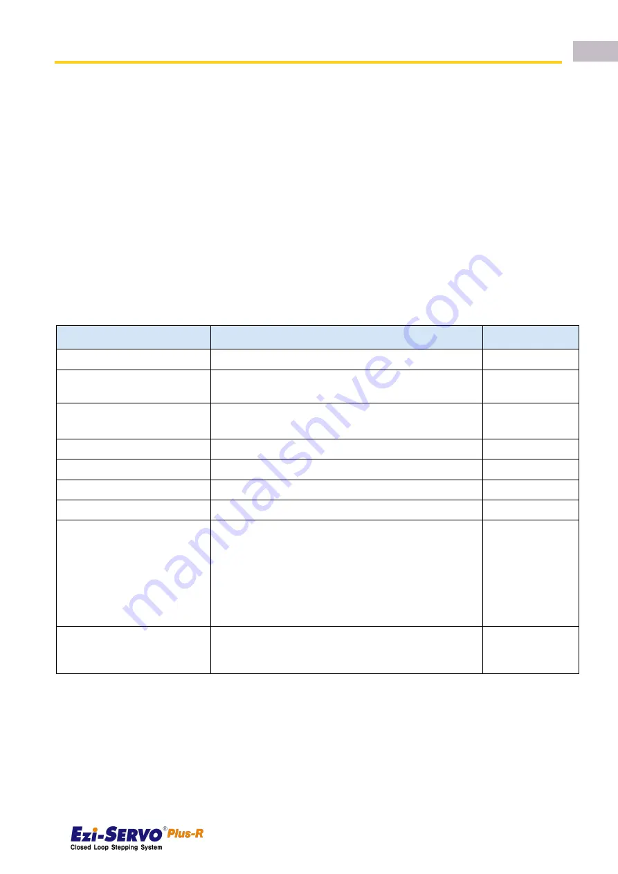
There is another library for status checking of push motioning. The position value that is
used in push motion must be
‘absolute coordinate’ value.
Setting Item
Description
Range *1
Position command Start speed
Start speed value of position motion
1~35000[pps]
Position
command
Moving
speed
Moving speed of position motion
1~500000[pps]
Position
command
Target
position
Absolute target position value of position command
134,217,727 ~
134,217,727
Acceleration time
Acceleration time of position motion
1~9,999[ms]
Deceleration time
Decelerate time of position motion
1~9,999[ms]
Push ratio
Motor torque value in push mode
20~80[%]
Push command Moving speed
Moving speed of Push motion (max 400[rpm])
1~66000[pps]
Push command Target
position
Absolute targett position value of push command.
*Non-stop mode : the value must be set more than
‘ Position command Target position’ value.
*The motor will stop if the position is exceed this value
even if the work is not detected.
134,217,727 ~
134,217,727
Push mode
Set Stop mode(0) or Non-stop mode(1~10000) after the
work detect. In case of Non-stop mode, the motor move
backward as much as this value[pulse] distances.
0~10,000
*1 : The unit of [pps] in this item is referenced to 10,000[ppr] encoder.
Input signal(PT Start) Method
Firstly the position table data must be entered before the push motioning and refer to
「
User
Manual
– Position Table Function
」
.
Summary of Contents for Ezi-Servo ALL
Page 1: ...www fastech co kr User Manual Text Ver 3...
Page 10: ...2 1 Driver Specification www fastech co kr 10 2 1 2 Ezi SERVO Plus R MINI...
Page 11: ...2 1 Driver Specification 11 www fastech co kr 2 1 3 Ezi SERVO ALL 28 series...
Page 12: ...2 1 Driver Specification www fastech co kr 12 2 1 4 Ezi SERVO ALL 42 56 series...
Page 13: ...2 1 Driver Specification 13 www fastech co kr 2 1 5 Ezi SERVO ALL 60 60 ABS series...
Page 17: ...3 2 Motor Dimension 17 www fastech co kr 3 2 Motor Dimension...
Page 18: ...3 2 Motor Dimension www fastech co kr 18...
Page 19: ...3 2 Motor Dimension 19 www fastech co kr...
Page 20: ...3 3 Motor Torque www fastech co kr 20 3 3 Motor Torque 3 3 1 Ezi SERVO Plus R...
Page 23: ...4 1 Part Numbering 23 www fastech co kr 3 Ezi SERVO ALL series...
Page 28: ...4 3 External Wiring Diagram www fastech co kr 28 4 3 2 Ezi SERVO Plus R 86mm...
Page 29: ...4 3 External Wiring Diagram 29 www fastech co kr 4 3 3 Ezi SERVO Plus R MINI...
Page 30: ...4 3 External Wiring Diagram www fastech co kr 30 4 3 4 Ezi SERVO ALL 28 series...
Page 31: ...4 3 External Wiring Diagram 31 www fastech co kr 4 3 5 Ezi SERVO ALL 42 56 series...
Page 32: ...4 3 External Wiring Diagram www fastech co kr 32 4 3 6 Ezi SERVO ALL 60 series...
Page 33: ...4 3 External Wiring Diagram 33 www fastech co kr 4 3 7 Ezi SERVO ALL 60 ABS...
Page 44: ...5 3 Ezi SERVO ALL 28 www fastech co kr 44 5 Network ID Setting 6 Connector Specifications...
Page 51: ...5 5 Ezi SERVO ALL 60 60 ABS series 51 www fastech co kr 8 Connector Specifications...