10
8
CONTROLS DESCRIPTION
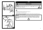
The mobile control stand (fig. C) enables the operator to work at any position around the machine. On this mobile
stand the following controls are located:
-
the joystick
1
(1, fig. C)
in position
A
let the chuck holder move away from the tool holder; in position
B
it moves
it in opposite direction; in position
D
it moves the chuck arm holder rightwards and the tool holder leftwards
simultaneously (so they get close to each other); in position
E
it moves the chuck arm holder leftwards and the
tool holder rightwards simultaneously (so they get far from each other).
-
The joystick 2 (2, fig. C)
controls all the tool’s movements; in position
F
(up) it brings the tool arm to “rest
position”; in position
G
(down) it brings the arm in “work position”; in position
H
(left) it controls 180° anti-clockwise
rotation of the tools; in position
I
(right) it controls opposite rotation so bringing the tools in the initial condition.
-
Switch 3
(3, fig. C)
if pushed up to position
L
it makes the chuck rotate at the double of the speed set when
selecting position
M
(up).
-
Switch 4 (4, fig. C)
let the chuck holder arm and the tool holder arm move at the same time either at high speed
(pos.
N
) or at reduced speed (pos.
O
)
-
Switch 5 (5, fig. C)
, if pushed up to pos.
P
, it let the chuck jaws open (LOCK), if pushed down to pos.
Q
it let
the chuck jaws close (UNLOCK)
-
Switch 6 (6, fig. C)
let the chuck move up (pos.
R
) and down (pos.
S
)
-
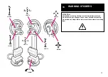
The balance pedal (7, fig. C)
let the chuck rotate in the direction shown by the arrow stuck on both pedal sides
(
T
and
U
).
REMARKS: all the controls available in the mobile column are very sensitive, so granting the smallest movement
with the highest precision.
On the tyre-changer,
knob (19, fig. D)
is also available for replacing the mounting tool whenever necessary (f.i. to
install the RT tubeless roller tool)
D
18
19
17
C
P
R
S
6
A
B
D
1
E
L
M
3
F
5
Q
N
O
4
H
G
I
2
U
T
7


