24
MOUNTING OPERATION WITH FINGER TOOL
1)
proceed as described in point 1,2,3,4,5 of “Mounting operation with disk” section.
2) Move the tool arm to rest position, then move it to the inner side of the tyre and hook it in this
position.
3)
The finger tool must be positioned at the wheel side, otherwise turn it by 180°
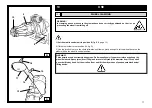
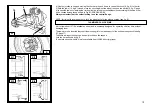
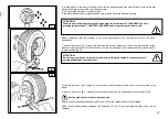
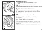
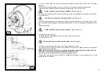
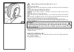
4) move the tool until the red spot is at the level of the rim outer edge, at a distance of about 5mm. from it (see fig.
O)
Set the mobile control unit in work position D
(fig. B/8, page
21)
Set the mobile control unit in work position C
(fig. B/8, page 21)
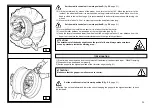
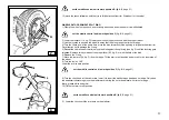
5) from the wheel outside have a visual check on tool position and correct it, if necessary. Then turn the
chuck
clockwise
until the gripper is in the lowest position (at 6 o’clock). The first bead will be inserted in
position.
6) remove the gripper
7) Let the tool out of the tyre
8) move the tool arm to rest position, then move it to the tyre outer side and hook it in this position
9) let the tool rotate by 180°
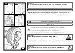
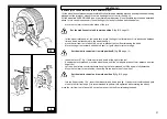
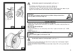
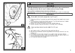
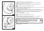
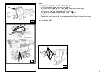
10) mount the gripper in the lowest position (at 6 o’clock) out of the second bead (see fig. N).
Set the mobile control unit in work position C
(fig. B/8, page
21)
Set the mobile control unit in work position C
(fig. B/8, page 21)
11) let the chuck rotate
clockwise
by 90° (until the gripper is at 9 o’clock)
12) move the tool until the red spot is at the level of the rim outer edge, at a distance of about 5mm. from
it. Start clockwise rotation checking the second bead that, after 90° rotation, shall start slipping into the
rim groove. Let rotate until the gripper is in lowest position (at 6 o’clock). Also the second bead will be
inserted in position.
13) proceed as described in point 11,12,13,14,15 of “mounting operation with disk” section to remove the
wheel correctly.
N
O


