27
T
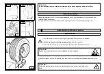
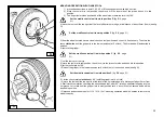
5) Lift the rim with hooked tyre and let it rotate counterclockwise of about 15-20 cm. The tyre will set itself
slantways.
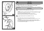
6) set the tool arm to rest position, then move it to the tyre inner side and hook it in this position.
7) make sure that the finger tool is positioned on the wheel side. If not, turn it by 180°
Set the mobile control unit in work position D
(fig. B/8, page 21)
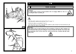
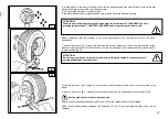
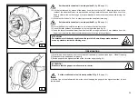
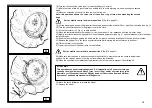
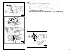
8) move the tool until the red spot in it is at the same level of the rim outer edge, at a distance of about 5mm.
from it (see Fig. S)
9) from the wheel outside have a visual check of the tool position and adjust it, if necessary. Then, turn the
chuck clockwise until the gripper is in the lowest position (at 6 o’clock). The first bead will be inserted in the
rim.
Remove the gripper.
Set the mobile control unit in work position C
(fig. B/8, page 21)
10) Pull the tool out of the tyre.
11) Set the tool arm in rest position and move it to the outer side of the tyre
12) Turn the tool by 180°
Set the mobile control unit in work position C
(fig. B/8, page 21)
13) Turn the chuck until the valve is set in the lowest position (at 6 o’clock)
14) Lower the chuck until the tyre rests on the platform; move the chuck slightly inwards as to create the
gap necessary to insert the tube.
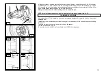
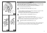
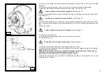
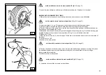
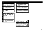
NOTE: the hole for the valve can be in asymmetrical position compared with the centre of the rim.
In this case, it is necessary to introduce the tube as shown in fig. T.
Insert the valve into the hole and fix it by means of the proper ring nut.
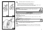
15) insert the tube into the rim groove (Note: to facilitate this operation it is recommended to do it while
turning the chuck clockwise).
Set the mobile control unit in work position C
(fig. B/8, page 21)
S

