Farm King 1342 Operator And Parts Manual Download Page 116

Parts Identification - 13” Conventional Auger

112

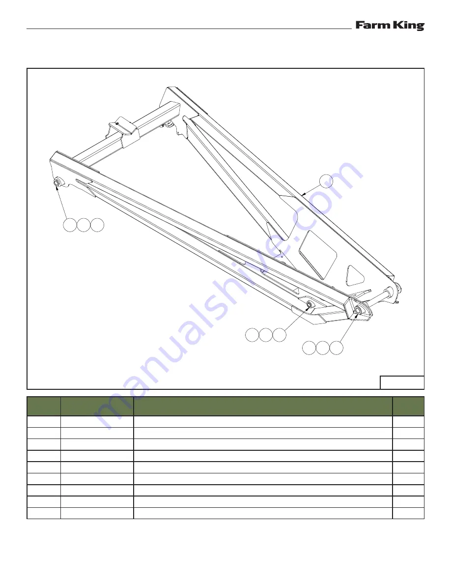
UPPER LIFT ARM - C1342, C1352

ITEM

PART NUMBER

DESCRIPTION

QTY.

1

81210

1/4" X 2" COTTER PIN (PL)

3

2

84522

1" ID SAE FLAT WASHER (PL)

1

3

960105

LIFT ARM PIVOT PIN WELDT 1.000" DIA

1

4

960110

SWIVEL PIN 1.250" DIA

2

5

960632

LIFT ARM PIVOT PIN WELDT 1.500" DIA

1

6

967135

1 1/2" RIM WASHER (10GA) (PL)

1

7

9812433

3/16" X 1 1/2" COTTER PIN

1

8

9812487

1 1/4" X 10GA NARROW RIM WASHER (PL)

2

9

F2592

WELDT-C1342/52 UPPER LIFT ARM

1

9

5

6

1

3

7

2

4

8

1

935885

Summary of Contents for 1342

Page 1: ...082020 FK422 OPERATOR AND PARTS MANUAL 13 CONVENTIONAL AUGER Models 1342 1352 1362 ...

Page 2: ......

Page 3: ...D 20 001 1 7 2020 C13 Y 7 29 2020 20 009 1 31 2020 C13 Y 7 29 2020 20 014 2 20 2020 C13 Y 7 29 2020 20 015 2 24 2020 C13 Y 7 29 2020 20 018 2 28 2020 C13 Y 7 29 2020 20 022 3 9 2020 C13 Y 7 29 2020 20 044 5 11 2020 C13 Y 7 29 2020 20 048 6 8 2020 C13 Y 7 29 2020 20 051 6 19 2020 C13 Y 7 29 2020 ...

Page 4: ... 13 Conventional Auger ii ...

Page 5: ...IFICATIONS 179 WARRANTY 185 Manufacturer s Statement For technical reasons Farm King reserves the right to modify machinery design and specifications provided herein without any preliminary notice Information provided herein is of descriptive nature Performance quality may depend on soil fertility applied agricultural techniques weather conditions and other factors ...

Page 6: ... 13 Conventional Auger 2 ...

Page 7: ... FlightingTurns Freely Gear Box Oil Level Checked All Fasteners AreTight Machine Is Lubricated CheckTire Pressure All Lights And Reflectors Installed All Lights And Reflectors Cleaned And Working Safety Chain On Hitch All Decals Installed Guards And Shields Installed And Secure Review Operating And Safety Instructions Check For Hydraulic Leaks Date Dealer Rep Signature The above equipment and Oper...

Page 8: ...Warranty Registration Form 13 Conventional Auger 4 ...

Page 9: ...ication of the Farm King equipment READ AND UNDERSTAND THIS OPERATOR AND PARTS MANUAL BEFORE OPERATING YOUR FARM KING EQUIPMENT If you have any questions see your Farm King dealer This manual may illustrate options and accessories not installed on your Farm King equipment OWNER S INFORMATION 7 Serial Number Location 7 Manual Storage 7 EQUIPMENT IDENTIFICATION 8 Component Location 8 ...

Page 10: ...Introduction 13 Conventional Auger 6 ...

Page 11: ...anty or guarantee of any kind written or expressed implied or otherwise with regard to the information contained within this manual Farm King assumes no responsibility for any errors that may appear in this manual and shall not be liable under any circumstances for incidental consequential or punitive damages in connection with or arising from the use of this manual Keep this manual available for ...

Page 12: ...Introduction 13 Conventional Auger 8 EQUIPMENT IDENTIFICATION Component Location INTAKE JACK WHEEL DISCHARGE SPOUT SCISSOR LIFT DRIVELINE HYDRAULIC CYLINDER 42 FT MODEL TOP DRIVE COVER GEARBOX ...

Page 13: ...Introduction 13 Conventional Auger 9 BRIDGING TRUSS CABLE 52 FT MODEL 62 FT MODEL ...

Page 14: ...Introduction 13 Conventional Auger 10 ...

Page 15: ...Safety Rules For PowerTake Off PTO Driven Equipment 14 Machine Requirements And Capabilities 15 Transport Safety 15 FIRE PREVENTION 16 Maintenance 16 Operation 16 Fire Extinguishers 16 Electrical 16 Hydraulic System 16 Fueling 16 Welding And Grinding 16 GAS ENGINE SAFETY 17 OPERATING SAFETY ZONE 18 Safety Zone Identification 18 EQUIPMENT SAFETY SIGNS 20 SAFETY SIGN OFF FORM 24 ...

Page 16: ...Safety 13 Conventional Auger 12 ...

Page 17: ... while working An operator who is taking prescription drugs must get medical advice to determine if he or she can safely operate a machine and the equipment Understand the written instructions rules and regulations The written instructions from Farm King include the Warranty Registration Dealer Inspection Report Operator And Parts Manual and machine signs decals Check the rules and regulations at ...

Page 18: ...n area clear of bystanders especially small children DO NOT permit personnel to be in the work area when operating the equipment The equipment must be used ONLY on approved tractors transport vehicles DO NOT modify the equipment in any way Unauthorized modification may impair the function and or safety and could affect the life of the equipment DO NOT make any adjustments or repairs on the equipme...

Page 19: ...l blocks underneath and support the equipment securely before working under raised equipment Keep bystanders clear of moving parts and the work area Keep children away Use increased caution on slopes and near banks and ditches to prevent overturn Make certain that the Slow Moving Vehicle SMV emblem is installed so that it is visible and legible When transporting the equipment use the flashing warn...

Page 20: ...lectrical Check all electrical wiring and connections for damage Keep the battery terminals clean and tight Repair or replace any damaged part or wires that are loose or frayed Battery gas can explode and cause serious injury Do not jump start or charge a frozen or damaged battery Keep any open flames or sparks away from batteries Do not smoke in battery charging area Hydraulic System Check hydrau...

Page 21: ...lug or spark plug wire removed DO NOT crank engine with spark plug removed If engine is flooded crank until engine starts DO NOT strike flywheel with a hard object or metal tool as this may cause flywheel to shatter in operation Use proper tools to service engine DO NOT operate engine without a muffler Inspect periodically and replace if necessary If engine is equipped with a muffler deflector ins...

Page 22: ...one clear when operating the hopper mover DANGER ELECTROCUTION HAZARD Keep away from power lines electrocution can occur without direct contact CAUTION Owners and operators should allow only authorized personnel and grain transport vehicles near the auger or inside the work area Allow adequate space for grain transport vehicles to operate safely Make certain everyone is clear of the equipment befo...

Page 23: ...Safety 13 Conventional Auger 19 ...

Page 24: ...w the instructions on all the signs decals that are on the equipment Replace any damaged signs decals and be sure they are in the correct locations Equipment signs are available from your Farm King equipment dealer Figure 3 INTAKE AUGER TOP VIEW 1 2 3 7 8 4 5 6 ...

Page 25: ... Auger 21 Tube Decal Identification Figure 3 105420 REFERENCE PLATE Item 1 909745 ELECTROCUTION Item 2 960569 UPENDING Item 3 961015 IMPORTANT Item 4 961016 HANDS AND FEET Item 5 961017 CAUTION Item 6 966699 GREASE NOT SHOWN ...

Page 26: ... 22 967055 AMBER REFLECTOR 2 X 9 NOT SHOWN 938128 MODEL 1342 Item 7 938127 MODEL 1352 938126 MODEL 1362 935029 FARM KING Item 8 Belt Decal Identification 909747 ROTATING HAZARD 915861 MISSING SHIELD HAZARD 966700 CAUTION NO RIDERS ...

Page 27: ...Safety 13 Conventional Auger 23 Gearbox Shifter Decal Identification 934111 REVERSIBLE GEARBOX 934112 REVERSIBLE GEARBOX ...

Page 28: ... ASABE and the Occupational Safety and Health Administration OSHA Anyone who will be operating and or maintaining the auger must read and clearly understand ALL Safety Operating and Maintenance information presented in this manual Annually review this information before the season start up and make these periodic reviews of SAFETY and OPERATION a standard practice for all of your equipment An untr...

Page 29: ...per Lift Arm All Models 42 Lower Lift Arms Undercarriage All Models 44 Wheels Stub Axles All Models 46 MOUNT ENGINE 47 Mount Engine 1352 1362 Models 47 Mount Engine 1342 Models 50 MOUNT PTO BELT 52 Mount PTO Belt 1342 Models 52 Mount PTO Belt 1352 1362 Models 53 MOUNT ELECTRIC MOTOR 54 Mount Electric Motor 1342 Models 54 Mount Electric Motor 1352 1362 Models 54 DRIVE ENGINE 55 Pivot Guard All Mode...

Page 30: ...1362 Models 65 BELTTRAYS 66 BeltTrays C1342 Models 66 BeltTrays C1352 C1362 Models 66 Bottom Guard All Models 67 BELT ROUTING 68 BELT COVERS 69 GUARD COVERS 70 HYDRAULIC CYLINDER HOSE ROUTING 71 GEARBOX SHIFTER BELT DRIVE MODELS 74 ELECTRICAL CABLES 76 Electric Clutch 76 E Stop 77 ...

Page 31: ...rom moving parts Always use lifting devices vehicles chains or straps of adequate size and strength when unloading and assembling components IMPORTANT Unload crate s and auger components carefully not to cause damage to any of the components Using the packing list locate and place all components and hardware in one area Count the individual components and verify that you have received the correct ...

Page 32: ...ssembling components IMPORTANT LEFT RIGHT FRONT REAR The directions left right front and rear as mentioned throughout this manual are as viewed as the operator sitting in the tractor s seat with the equipment hitched to the tractor Figure 5 Raise and move the top and bottom tube sections to the assembly area using an approved lifting device Item 1 Figure 5 Place cardboard Item 2 where the tube con...

Page 33: ...m the intake tube Turn the flighting using an appropriate tool Item 1 Align the intake tube flighting edge Item 2 with the discharge tube flighting edge Item 3 Figure 7 Figure 8 Slide the intake tube flighting Item 1 onto the square shaft Item 2 Figure 8 Figure 9 Attach the flighting using one 1 2 x 4 hex bolt and one 1 2 lock nut Item 1 Figure 9 1 DISCHARGETUBE 2 DISCHARGETUBE INTAKETUBE INTAKETU...

Page 34: ...0 IMPORTANT The flange bolt threads must face towards the intake Tighten the flange bolts evenly around the tube in a criss cross pattern Figure 11 Install the jack stand to the intake tube mount Figure 11 Figure 12 Place the clamps of the intake cage over the intake tube The clamps must be placed past the tab Item 1 on the intake tube Figure 12 Attach the clamps using six 3 8 x 1 3 4 hex bolts It...

Page 35: ...iveline Install two 5 16 x 1 4 setscrews Item 2 to the collar Do not tighten at this time Figure 14 Figure 15 Align the gearbox Item 1 to the tube mount The splined shaft must face the driveline The slotted shaft must face left Figure 15 Do not attach hardware Figure 16 Place the gearbox shield Item 1 over the slotted shaft Item 2 Align with the holes on the top of the gearbox Figure 16 Models Wit...

Page 36: ... not attach at this time Figure 19 Install one 5 16 SQ x 58 mm key Item 2 to the driveline slot Figure 19 Install one slotted sprocket Item 3 to the driveline Figure 19 Install one spline sprocket Item 4 to the gearbox shaft Figure 19 IMPORTANT Make sure each sprocket is flush with shaft Tighten set screws Make sure each sprocket remains flush with shaft while adjusting Figure 17 Attach the gearbo...

Page 37: ... 1 down the length of the driveline Pull the couplings OUT or push IN to adjust Figure 21 Tighten set screws Item 3 once adjustments are finished with the sprockets and chain coupling properly aligned Figure 21 IMPORTANT Adjust the couplings EVENLY down the length of the driveline The slot Item 2 can be visible on the driveline Figure 21 The key must NOT be visible in the slot The driveline and co...

Page 38: ...e previous shield section and be hooked underneath each bearing mount Figure 23 For augers equipped with light kit The electrical cable is routed below the driveline to the work light Cable clamps Item 1 will need to be installed to the mounts before the driveline shields See light kit instruction manual Figure 23 Figure 24 Place the last driveline shield Item 1 The last driveline shield will rest...

Page 39: ...gure 26 GEARBOX PTO DIRECT DRIVE Figure 27 Direct Drive Models Install the PTO shield Item 1 to the gearbox using four 5 16 x 3 4 hex bolts four 5 16 flat washers and four 5 16 lock nuts Figure 27 Figure 28 Install the PTO holder Item 1 to the auger tube Attach using two 3 8 x 1 hex bolts Item 2 Figure 28 Position the PTO holder facing the same side as the gearbox shaft Attach one PTO holder pin a...

Page 40: ... 1 X 7 16 flat washers and clamp nuts Figure 30 Figure 31 Connect the cable Item 1 to the eye bolt Item 2 Figure 31 Attach the eye bolt to the mount on the intake tube using one lock nut Item 3 Figure 31 Only tighten the nut past the first few threads of the eye bolt to leave room for tightening Repeat on other side Figure 32 Connect the cable Item 1 to the bracket Item 2 Figure 32 Pull the cable ...

Page 41: ... eye bolt Item 1 and tighten the lock nut Item 2 Figure 33 Tighten the cable Repeat on other side Tighten the cables evenly IMPORTANT DO NOT bow the tube when tightening WARNING Wear proper hand protection when handling and tightening cables 1 2 INTAKETUBE ...

Page 42: ...Assembly 13 Conventional Auger 38 DISCHARGE SPOUT Figure 34 Slightly raise and secure the tube Attach the discharge spout Item 1 using six 3 8 x 2 hex bolts Item 2 and six 3 8 lock nuts Figure 34 1 2 ...

Page 43: ...em 3 Figure 36 Do not tighten bolts at this time Figure 37 Position the upper cross braces Place one cross brace Item 1 on top of the mounts Figure 37 Place one cross brace Item 2 below the mounts Figure 37 Attach the ends of the braces to the undercarriage using four 1 2 x 1 1 2 hex bolts Item 3 four 1 2 flat washers and four 1 2 lock nuts Figure 37 Attach the center of the cross braces Item 4 to...

Page 44: ...ch the center of the cross braces Item 4 together using 1 2 x 1 1 2 hex bolts 1 2 flat washers and 1 2 lock nuts Figure 38 Do not tighten bolts at this time Figure 39 Position one cross plate Item 1 above the vertical mounts Attach using four 3 8 x 1 hex bolts Item 2 and four 3 8 lock nuts Figure 39 Position two cross plates Item 3 on the horizontal mounts Place one plate above the mounts and one ...

Page 45: ...ts Item 3 Figure 41 Do not tighten bolts at this time IMPORTANT Install all undercarriage bolts with threads facing DOWN where possible DO not tighten undercarriage bolts at this time Figure 42 Position one cross plate Item 1 above the vertical mounts Attach using four 3 8 x 1 hex bolts Item 2 and four 3 8 lock nuts Figure 39 Position two cross plates Item 3 on the horizontal mounts Place one plat...

Page 46: ...he tube high enough to move the upper lift arm underneath and into position WARNING DO NOT work under suspended parts Always use lifting devices vehicles chains or straps of adequate size and strength Figure 44 Move the upper lift arm underneath the auger tube Align the pivot holes Item 1 with the correct tube mounts depending on model Figure 44 See tube mounts Figure 46 Figure 45 Attach the upper...

Page 47: ... Models use Mount 1 1362 Models use Mount 2 Figure 47 Raise the upper lift arm Item 1 and secure to the auger tube using straps Item 2 of adequate size and strength Figure 47 WARNING DO NOT work under suspended parts Always use lifting devices vehicles chains or straps of adequate size and strength 1342 MODEL 1352 MODEL 1362 MODEL MOUNT 2 MOUNT 2 MOUNT 2 MOUNT 1 MOUNT 1 MOUNT 1 1 1 1 2 1 ...

Page 48: ... 50 Figure 51 Refasten the undercarriage cross members Figure 51 Do not tighten bolts at this time Lower Lift Arms Undercarriage All Models Figure 48 Move the undercarriage assembly Item 1 underneath the tube Position the pivot brackets Item 2 with the tube mounts Item 3 Figure 48 Figure 49 Unfasten the cross members at the mounts Item 1 on one side of the undercarriage assembly to allow installat...

Page 49: ...her and cotter pin Figure 53 Figure 54 Position the cross braces Place one cross brace Item 1 on top of the mounts Figure 54 Place one cross brace Item 2 below the mounts Figure 54 Attach the ends of the braces to the lower lift arms using four 1 2 x 1 1 2 hex bolts Item 3 four 1 2 flat washers and four 1 2 lock nuts Figure 54 Place the beam brace Item 4 between the lower lift arms Attach using ei...

Page 50: ... manual cannister Item 1 to the cross brace using two 5 16 x 1 1 4 hex bolts Item 2 two 5 16 flat washers and two 5 16 lock nuts Figure 56 Wheels Stub Axles All Models Figure 57 Align the LH and RH stub axles Item 1 to the axle mounts Attach each stub axle using four 1 2 x 2 hex bolts Item 2 and four 1 2 lock nuts Figure 57 Figure 58 Raise the axle using an approved lifting device Attach the wheel...

Page 51: ... 3 Figure 60 Repeat to install a second plate on the other side of the motor mount MOUNT ENGINE Mount Engine 1352 1362 Models Figure 59 Fit the square portions of two guide weldments Item 1 around the axle Item 2 Make sure the grease holes Item 3 are facing outwards Figure 59 Attach the weldments using four 3 8 x 1 1 2 hex bolts and four 3 8 lock nuts Repeat to install a second set of guide weldme...

Page 52: ...ight front and rear as mentioned throughout this manual are as viewed by the operator sitting in the tractor seat while towing the implement IMPORTANT Contact your dealer for proper engine installation Your specific engine may not be depicted WARNING DO NOT work under suspended parts Always use lifting devices vehicles chains or straps of adequate size and strength Figure 63 Position the battery h...

Page 53: ...e 65 Angle the mount towards the intake Figure 66 Position two brackets Item 1 around the axle to the bottom of the fuel tank mount Attach bracket using two 3 8 x 1 hex bolt Item 2 and two 3 8 lock nut Figure 66 Figure 67 Place the fuel tank Item 1 within the mount Make sure the fuel fittings Item 2 face the engine Figure 67 Position two straps Item 3 over the tank Attach each strap to the mount u...

Page 54: ... halves Item 4 on the outside of the mount Attach each pair of bracket halves using two 3 8 x 1 1 4 and two 3 8 lock nuts Figure 69 Prepare the engine for installation Move the engine onto the mount using a lifting device of adequate size and strength Position the engine drive facing left Make sure the mount is supported with stands Item 5 of adequate size and strength Figure 69 Install the engine...

Page 55: ...und the axle and to the bottom of the mount Attach each bracket to the mount using two 5 16 x 1 hex bolts and two 5 16 lock nuts Figure 70 Place the fuel tank Item 3 within the mount Make sure the hose fittings face the engine Figure 70 Install two straps Item 4 over the fuel tank Attach each strap to the mount using two 5 16 x 1 hex bolts and two 5 16 lock nuts Figure 70 2 1 3 4 DISCHARGE ...

Page 56: ...2 See Figure 69 to install mount Position the plate Item 3 on the side of the mount Attach using four 3 8 x 1 hex bolts and four 3 8 lock nuts Figure 72 Align two pillow bearings Item 4 with the side plate and holes on top of the mount Attach each pillow bearing using two 1 2 x 2 hex bolts two 1 2 flat washers and two 1 2 lock nuts Figure 72 Slide the PTO shaft Item 5 through the side plate and pi...

Page 57: ...e the PTO drive mount Item 1 and mounting plates Item 2 on the axle Figure 73 See Figure 59 Figure 60 and Figure 61 to install the mounting plates Install the PTO drive shaft Item 3 and bearings on top of the mount Figure 73 See Figure 72 to install the PTO drive 2 2 1 3 DISCHARGE ...

Page 58: ...4 Figure 75 Position the motor mount Item 1 on the cross brace Attach two plates Item 2 on the inside of the mount and around the cross brace Figure 75 See Figure 69 to install mount Mount Electric Motor 1352 1362 Models Figure 76 Place the motor mount Item 1 and mounting plates Item 2 on the axle Figure 76 See Figure 59 Figure 60 and Figure 61 to install the mounting plates Motor spacers Item 3 a...

Page 59: ...of the slide plate with the slots of the pivot guard Item 4 Figure 77 Attach the slide plate to the slots using four 5 16 x 1 carriage bolts and four 5 16 lock nuts Item 5 Place the carriage bolts within the slots Figure 77 Thread one 5 8 flat washer onto the adjustment bolt then one 3 4 hex nut Item 6 after the washer Figure 77 Figure 78 Place the mounting plate Item 1 on the outside of the pivot...

Page 60: ...e grease slots Item 4 are positioned at the top and bottom Figure 80 Figure 81 Place the outer ring plate Item 1 on top of the other ring plates Align the holes Figure 81 Install two grease zerks Item 2 to the top and bottom holes Figure 81 Install four 7 16 x 1 1 4 flat head screws Item 3 and four 7 16 lock nuts to the corner holes Figure 81 Install two 1 4 x 1 hex bolts Item 4 and two 1 4 lock n...

Page 61: ...at head screws Item 3 Figure 82 Note Tighten screws in a criss cross pattern Figure 83 Attach the housing plate Item 1 over the engine PTO using flat head screws Item 2 Figure 83 Install one 1 2 x 1 2 x 2 1 4 key Item 3 to the PTO shaft Figure 83 Figure 84 Position the pivot guard Item 1 over the PTO shaft Align the mounting plate with the side of the engine mount Attach using six 5 16 x 1 carriag...

Page 62: ... 2 using four 3 8 x 2 1 2 flat head screws Item 3 Figure 85 Figure 86 Place one 1 415 long spacer Item 1 onto the shaft Place the electric clutch and pulley Item 2 onto the shaft Figure 86 Figure 87 Place the 1 805 long stub shaft Item 1 into the electric clutch opening Item 2 Figure 87 1 2 1 2 3 1 2 1 L 1 415 ...

Page 63: ...bracket using one 1 4 x 3 4 hex bolt and 1 4 lock nut Figure 89 Drive Engine 1342 Models IMPORTANT Contact your dealer for proper engine installation The following may not depict your specific engine Figure 90 Position the mounting plate Item 1 over the PTO shaft Align the plate with the holes on the side of the engine mount Attach using five 5 16 x 1 carriage bolts Item 2 and five 5 16 lock nuts ...

Page 64: ...2 Make sure the engine PTO shaft is centered in the opening of the guard Figure 92 Install one 1 4 x 1 4 x 1 1 2 key Item 1 to shaft Figure 92 Figure 93 Place one 2 813 long spacer Item 1 onto the shaft Place the electric clutch and pulley Item 2 onto the shaft Figure 93 Figure 94 Place the 2 050 long stub shaft Item 1 into the electric clutch opening Figure 94 1 2 1 1 1 2 3 ...

Page 65: ...ind the electric clutch tab Attach using one 1 4 x 1 1 2 cotter pin Item 2 two 1 4 flat washers both sides of bracket and one plastic grommet outside of tab Figure 96 Attach the bracket to the guard using two 5 16 x 1 carriage bolts and two 5 16 lock nuts Item 3 Figure 96 Attach one P clip Item 4 to the bracket using one 1 4 x 3 4 hex bolt and 1 4 lock nut Figure 96 1 2 1 2 4 3 ...

Page 66: ... triple sheave C1352 C1362 PTO belt models 16 double sheave C1342 Pulley Thread one 3 8 hex nut each onto two 3 8 set screws Thread the set screws into the pulley base and tighten Back the hex nuts off and tighten against the pulley Figure 97 C1352 C1362 Pulley Align the holes of one pulley bushing Item 5 to the pulley Item 6 Attach the bushing using three screws Figure 97 Figure 98 Position the s...

Page 67: ...plate with the holes on the side of the engine mount Attach using five 5 16 x 1 carriage bolts Item 2 and five 5 16 lock nuts Figure 99 Note Attach using the top set of holes on the motor mount Only use the bottom set of holes for shorter style motors Assemble the ring plates Item 3 and pivot guard Item 4 See Figure 77 to Figure 81 1 2 3 4 ...

Page 68: ...the hex nuts off and tighten against the holder ring Figure 101 Install one pulley key Item 3 to the drive shaft Figure 101 C1342 3 8 x 3 8 x 3 3 8 pulley key C1352 C1362 3 8 x 3 8 x 2 pulley key Top Pulley C1342 Models Figure 102 Install the top pulley Item 1 depending on model Figure 102 PTO belt models 12 triple sheave Electric motor models 6 triple sheave Engine models 18 double sheave Thread ...

Page 69: ... pulley bushing Item 1 to the pulley Item 2 Attach the bushing using three screws Figure 103 Use pulley depending on model PTO belt models 16 double sheave Electric motor models 16 double sheave Engine models 16 double sheave Install the pulley and bushing to the gearbox shaft Figure 103 1 1 2 2 3 ...

Page 70: ...tem 1 and lower belt tray Item 2 face upwards Figure 105 Note C1342 Model belt trays are single pieces 1 2 2 2 1 TOP BELT GUARD GEARBOX BeltTrays C1352 C1362 Models Figure 106 Install the upper belt tray Item 1 and lower belt tray Item 2 to the top belt guard Attach each tray to the slots Item 3 using two 5 16 x 3 4 carriage bolts within the slots two 5 16 flat washers and two 5 16 lock nuts Figur...

Page 71: ... trays are slightly angled together PTO Drive Models Brace sides are equal length Bottom Guard All Models Figure 109 Align the slots on the bottom guard with the correct holes of the belt tray Install two 5 16 x 1 carriage bolts Figure 109 Use correct holes depending on model Figure 109 Engine models holes 2 and 3 Electric motor models holes 2 and 3 PTO belt models holes 4 and 5 Figure 110 Install...

Page 72: ...box Figure 112 Figure 113 Make sure the belts Item 1 are centered and floating in the trays Figure 113 IMPORTANT Belts must not be in contact with the trays Adjust the trays up or down using the slotted mounts on the guards Item 1 Figure 110 Make sure the belt trays are straight and parallel with the auger tube IMPORTANT Straighten the belt trays by adjusting Engine motor mount position left right...

Page 73: ... are placed correctly Attach the covers using Item 2 Figure 114 C1342 3 8 x 4 hex bolt and 3 8 lock nut C1352 C1362 5 16 x 4 1 2 hex bolt and 5 16 lock nut Figure 115 C1352 C1362 Overlap the two cover sections Item 1 at the center of the belt trays Attach using 5 16 x 4 1 2 hex bolt Item 2 and 5 16 lock nut Figure 115 Note C1342 units use only one cover section 1 1 2 2 1 2 1 2 ...

Page 74: ...at washers Figure 118 Install the back cover Item 1 using 5 16 x 3 4 hex bolts Item 2 and 5 16 lock nuts Figure 118 Note C1342 units with electric motor use 5 16 x 1 hex bolts and 5 16 lock nuts Figure 119 PTO belt models Place the cover Item 1 over the pivot guard Attach using four 5 16 x 3 4 hex bolts Item 2 and four 5 16 flat washers Figure 119 Attach the PTO shield Item 3 using four 5 16 x 3 4...

Page 75: ...e 120 One plug 8 ORB Apply teflon tape to all threaded hydraulic fittings Figure 121 Position the hydraulic cylinder to the tube and lift arm Attach the rod end Item 1 of the cylinder to the tube mount using Figure 121 C1342 C1352 1 flat washer 1 D pivot pin and 3 16 x 1 1 2 cotter pin C1362 1 1 2 rim washer 1 1 2 D pivot pin and 1 4 x 2 cotter pin Attach the barrel end Item 2 of the cylinder to t...

Page 76: ...Direct drive models Attach the mounting bracket with shut off valve to the gearbox mount using two 1 4 x 3 4 hex bolts Item 1 two 1 4 flat washers and two 1 4 lock nuts Figure 124 Route the hose Item 2 from the enclosed tube around the gearbox mount and to the shut off valve Figure 124 Connect one hydraulic hose Item 3 to the shut off valve Route the hose to the storage bracket and to the tractor ...

Page 77: ... the shut off valve Figure 124 Connect one hydraulic hose Item 3 to the shut off valve Route the hose to the storage bracket and to the tractor Figure 124 Figure 126 Connect one 8MPT x 4MJIC adapter Item 1 and one quick connector Item 2 to the hose leading to the tractor Figure 126 2 1 ...

Page 78: ...ch to the bracket using one 3 8 x 1 1 4 hex bolt Item 2 two 3 8 flat washers both sides and one 3 8 lock nut Figure 128 Place two rubber grips Item 3 onto each end of the handle Figure 128 Figure 129 Attach the inner shifter link Item 1 to the handle using one 3 8 x 1 1 4 hex bolt Item 2 two 3 8 flat washers both sides and one 3 8 lock nut Figure 129 Figure 130 Insert the inner Item 1 and outer It...

Page 79: ...1 to the gearbox using one 3 8 x 1 1 4 hex bolt Item 2 two 3 8 flat washers both sides and one 3 8 lock nut Figure 129 IMPORTANT Make sure the shifter handle and the gearbox are both in the center position Tighten the socket set screw of the shifter link 2 1 SHIFTER HANDLE GEARBOX ...

Page 80: ... hex bolt and 1 4 lock nut Figure 132 Attach the male connector of the wire harness to the electric clutch connector Item 3 Figure 132 Figure 133 Route the wire harness from the hole Item 1 in the belt guard Figure 133 Attach the wire harness to the side of the belt guard using one p clip Item 2 1 4 x 3 4 hex bolt and 1 4 lock nut Figure 133 IMPORTANT Connect wire harness to engine battery dependi...

Page 81: ...ictured Route the harness from the engine mount along the axle and inside the weldment tube All Models Pass the harness within the weldment tube exit the weldment where the weldment mounts to the auger tube Figure 133 Route one harness section Item 3 down the top of the weldment Route the harness section Item 4 to the E stop connector Figure 133 Route the remaining harness section Item 5 to the au...

Page 82: ... tube Route harness inside the tube Item 2 and towards the intake Figure 135 Route the harness Item 3 from the tube and along the underside Figure 135 Route harness to electric clutch and e stop connector Item 4 Figure 135 EXIT WELDMENT TUBE ROUTE INSIDE TUBE E STOP AND ELECTRIC CLUTCH CONNECTOR 1 2 3 4 ...

Page 83: ...ITION 84 EnteringThe Operator s Position 84 LeavingThe Operator s Position 84 HITCHING UNHITCHING 84 HitchingThe Equipment 84 UnhitchingThe Equipment 85 RAISING LOWERING AUGER 86 PTO BELT DRIVE DIRECT DRIVE 87 Connecting PTO Shaft 87 Disconnecting PTO Shaft 87 ELECTRIC CLUTCH 88 SHIFTING GEARBOX 88 EMERGENCY STOP 89 FIELD OPERATION 90 Working Position 90 Auger Operation 91 TRANSPORTING 92 ...

Page 84: ...Operation 13 Conventional Auger 80 ...

Page 85: ... Tools are being used 1 Lubricate the equipment per the schedule outline in the Maintenance Section 2 Check the augers Remove any material build up or debris that has become entangled 3 Make sure that all guards and shields are in place secured and functioning as designed WARNING HIGH PRESSURE FLUID HAZARD Leaking fluids under pressure can enter the skin and cause serious injury or death Immediate...

Page 86: ... using PTO driven equipment Disengage PTO for road travel Keep hands feet and clothing away Check the following mechanical items after one hour of operation and again after ten hours of operation 1 Re torque wheel bolts to proper torque and check tire pressure 2 Check for loose fasteners and hardware Tighten as required 3 Check the belt tension and alignment Tension or align as required 4 Check th...

Page 87: ...weight and total weight of the auger models The tractor tow vehicle must be rated for the listed weight to transport the specified auger model PTO drive model recommendations 60 HP tractor horsepower 1 3 8 21 spline PTO Engine drive model recommendations C1342 models CH980 Kohler 35 HP C1352 C1362 models Diesel Hatz 3H50TIC Electric motor recommendations Dealer provided IMPORTANT Contact your deal...

Page 88: ... children are in the work area Do not allow anyone between the tractor and the equipment when backing up to the equipment for connecting Leave the operator s position see Leaving The Operator s Position on page 84 ENTERING LEAVINGTHE OPERATOR S POSITION EnteringThe Operator s Position Enter the operator s position start the engine and release the parking brake IMPORTANT Follow the instructions in ...

Page 89: ... upending IMPORTANT Do not move the auger while in the raised position Lower the auger to the lowest position before moving See Raising And Lowering The Auger on page 86 Figure 139 Lift the intake and hitch to the tractor drawbar height Align the tractor hitch pin holes with the auger hitch pin holes Install the drawbar pin and retainer pin Item 1 Figure 139 Install the safety chain to the tractor...

Page 90: ...page 84 Place chocks in the front and rear of each wheel WARNING Always raise or lower the auger while hitched to a tractor or approved transport unit Never attempt to raise or lower the auger during operation Never place blocks under the wheels to increase the elevation of auger Keep wheels of undercarriage level and on firm ground DANGER ELECTROCUTION HAZARD To prevent serious injury or death fr...

Page 91: ...lace Install PTO driveline safety chain Item 2 Figure 141 WARNING AVOID INJURY OR DEATH Do NOT exceed 1000 RPM PTO Keep PTO shields and all guards in place Keep away from moving parts Keep bystanders away 1 2 Disconnecting PTO Shaft Disengage the PTO and lower engine RPM speed WARNING AVOID INJURY OR DEATH Wait for all moving parts to stop before disconnecting PTO Remove safety chain Item 2 Figure...

Page 92: ...amage to the equipment SHIFTING GEARBOX Figure 143 Shifting gearboxes are equipped with three settings Normal Setting Item 1 Figure 143 The flighting moves material from the intake to the discharge spout This setting should be used for normal operation Neutral Setting Item 2 Figure 143 The flighting is stopped Reverse Setting Item 3 Figure 143 The flighting will reverse and move any material in th...

Page 93: ...r pull up on the lock Item 1 and act on the shifter handle Item 2 to change gearbox settings Figure 144 NOTE Make sure the lock pin is securely in place at the desired setting EMERGENCY STOP Figure 145 Engine drive models are equipped with an emergency stop Item 1 Figure 145 1 1 2 ...

Page 94: ... and bystanders out of this area Stop the machine immediately if anyone enter this area Back the machine up to the storage facility while it is in its lowered configuration Use the hydraulic or manual winch to slowly raise the machine into position see Raising Lowering Auger on page 86 Figure 146 Slowly back the machine until the discharge spout Item 1 is over the opening in the storage facility F...

Page 95: ...wly engage the PTO clutch 4 Start the flow of material and unload 5 Increase engine speed to a rated PTO speed of 1000 rpm 6 Stop unloading 7 Run until the auger is empty 8 Reduce engine speed to low idle 9 Disengage PTO clutch 10 Shut off engine and remove ignition key Gas Engine Model 1 Disengage auger drive 2 Move the throttle to its mid range position 3 Close the choke if the engine is cold or...

Page 96: ...all lights and reflectors are clean and visible Enter the operator s position start the engine and release the parking brake Engage the tractor hydraulics see the tractor s operator s manual for the correct procedure Fully raise the toolbar into transport position WARNING AVOID SERIOUS INJURY OR DEATH DO NOT transport loaded equipment on public roadways Excess weight will greatly increase tractor ...

Page 97: ... 97 BELTTENSION 98 Engine DriveTension 98 PTO Belt DriveTension 98 PTO DRIVE BEARING COLLAR 99 GEARBOX OIL 100 AXLES 101 Wheel BoltTorque 101 Tire Wheel Replacement 101 Tire Pressure 102 STORAGE AND RETURNTO SERVICE 103 Storage 103 ReturnTo Service 103 SAFETY SIGN DECAL INSTALLATION 103 Procedure 103 ...

Page 98: ...Maintenance 13 Conventional Auger 94 ...

Page 99: ...eshooting section please call your local Farm King dealer Before you call please have this Operator And Parts Manual and the serial number of your machine at hand PROBLEM CAUSE CORRECTION Auger will not run No power Engage disengage electric clutch Check wiring Start gas engine or tractor and engage control Drive belt loose Adjust drive belt tension No fuel Refuel gas engine or tractor Broken shea...

Page 100: ...equipment Follow warnings and instructions in the manuals when making repairs adjustments or servicing Check for correct function after adjustments repairs or service Untrained operators and failure to follow instructions can cause injury or death DESCRIPTION SERVICE PROCEDURES Check Clean Lube Change Cover Repack Daily Maintenance or every 8 hours of use 1 PTO Shaft Weekly or every 50 hours of us...

Page 101: ...necessary IMPORTANT Fluid such as engine oil hydraulic fluid coolants grease etc must be disposed of in an environmentally safe manner Some regulations require that certain spills and leaks on the ground must be cleaned in a specific manner See local state and federal regulations for the correct disposal Figure 150 Lubricate the chain case Item 1 monthly or every 100 hours of use Figure 150 Figure...

Page 102: ... the adjustment bolt Item 2 Figure 153 Re tighten slider bolts Reinstall the upper and lower covers from the belt trays PTO Belt DriveTension Figure 154 Remove the upper and lower covers from the belt trays Check the belt tension Belts should be tight Loosen the slider bolts Item 1 Tighten or loosen the adjustment bolts Item 2 Figure 153 Re tighten slider bolts Reinstall the upper and lower covers...

Page 103: ...ING COLLAR Figure 155 Tighten the bearing collar Item 1 Figure 155 IMPORTANT CORRECT Tighten the bearing collar in the direction of shaft rotation INCORRECT Bearing collars depicted do not show exact PTO belt drive components but procedure is correct 1 ...

Page 104: ...heck the gearbox oil level Remove the drain plug Item 1 from the side of the gearbox Figure 156 Oil level should be just touching the threads Add oil through the fill plug Item 2 as required Figure 156 Reinstall drain and fill plugs Use SAE 80W90 synthetic oil 2 1 ...

Page 105: ...at level surface Place all controls in neutral engage the park brake stop the engine and wait for all moving parts to stop Leave the operator s position WARNING AVOID INJURY OR DEATH Always chock tires before performing any maintenance or service Place chock blocks behind and in front of the opposite tire to be removed Raise axle frame with jack until the tire wheel is slightly off the ground NOTE...

Page 106: ...2 Tire Pressure CAUTION When inflating tires use a clip on chuck and extension hose long enough to allow you to stand to one side and NOT in front of or over the tire assembly Check tire pressure daily Recommended tire pressure is 60 psi ...

Page 107: ... if required ReturnTo Service After the equipment has been in storage it is necessary to follow a list of items to return the equipment to service Be sure all shields and guards are in place Lubricate the equipment Connect to a tractor and operate equipment verify all functions operate correctly Check for leaks Repair as needed SAFETY SIGN DECAL INSTALLATION Procedure IMPORTANT When replacing safe...

Page 108: ...Maintenance 13 Conventional Auger 104 ...

Page 109: ...2 126 TUBES BELT DRIVE C1342 130 TUBES BELT DRIVE C1352 134 TUBES BELT DRIVE C1362 138 TUBE SECTIONS 142 BottomTube Direct Drive C1342 142 BottomTube Direct Drive C1352 143 BottomTube Direct Drive C1362 144 BottomTube Belt Drive C1342 145 BottomTube Belt Drive C1352 146 BottomTube Belt Drive C1362 147 TopTube All Units 148 PTO BELT DRIVE C1342 150 PTO BELT DRIVE C1352 C1362 154 ELECTRIC MOTOR DRIV...

Page 110: ...Parts Identification 13 Conventional Auger 106 AXLE STUB W HUB 175 HUB 176 WHEEL ANDTIRE 177 ...

Page 111: ...Parts Identification 13 Conventional Auger 107 ...

Page 112: ...ION The parts identification section list descriptions part numbers and quantities for all North America Base Model 13 Conventional Series Augers Contact your Farm King dealer for additional parts information UNDERCARRIAGE C1342 DETAIL A A 9 5 4 3 6 2 8 8 7 10 3 1 935097 ...

Page 113: ... HEX BOLT PL 4 2 812363 3 8 LOCK NUT PL 8 3 812364 1 2 LOCK NUT PL 20 4 84277 1 2 X 1 1 2 HEX BOLT PL 16 5 F2549 WELDT C1362 AXLE 1 6 86170 3 8 X 1 HEX BOLT GR 5 PL 8 7 910287 HOOK SAFETY CHAIN ASSEMBLY 1 8 937106L PLATE C13 U C CROSS 2 9 937343 WELDT C1342 U C ARM 2 10 937483 WELDT LIGHT STAND 2 ...

Page 114: ...Parts Identification 13 Conventional Auger 110 UNDERCARRIAGE C1652 C1362 DETAIL A A 10 11 6 5 3 1 12 3 7 2 8 9 5 3 4 5 3 4 13 934782 ...

Page 115: ...1 2 LOCK NUT PL 30 4 84048 1 2 SAE FLAT WASHER PL 12 5 84277 1 2 X 1 1 2 HEX BOLT PL 26 6 F2549 WELDT C1362 AXLE 1 7 86170 3 8 X 1 HEX BOLT GR 5 PL 12 8 910287 HOOK SAFETY CHAIN ASSEMBLY 1 9 935907 PLATE C13 CROSS BRACE 2 10 937102 WELDT C1362 U C ARM 2 11 937106L PLATE C13 U C CROSS 3 12 937483 WELDT LIGHT STAND 2 13 938046 PLATE C13 CROSS BRACE 2 ...

Page 116: ... 84522 1 ID SAE FLAT WASHER PL 1 3 960105 LIFT ARM PIVOT PIN WELDT 1 000 DIA 1 4 960110 SWIVEL PIN 1 250 DIA 2 5 960632 LIFT ARM PIVOT PIN WELDT 1 500 DIA 1 6 967135 1 1 2 RIM WASHER 10GA PL 1 7 9812433 3 16 X 1 1 2 COTTER PIN 1 8 9812487 1 1 4 X 10GA NARROW RIM WASHER PL 2 9 F2592 WELDT C1342 52 UPPER LIFT ARM 1 9 5 6 1 3 7 2 4 8 1 935885 ...

Page 117: ...TY 1 81210 1 4 X 2 COTTER PIN PL 4 2 960110 SWIVEL PIN 1 250 DIA 2 3 960628 BOTTOM CYL PIN WELDT 1 500 DIA 1 4 960632 LIFT ARM PIVOT PIN WELDT 1 500 DIA 1 5 967135 1 1 2 RIM WASHER 10GA PL 2 6 9812487 1 1 4 X 10GA NARROW RIM WASHER PL 2 7 F2579 WELDT C1362 UPPER LIFT ARM 1 7 4 5 1 3 5 1 2 6 1 935740 ...

Page 118: ...Parts Identification 13 Conventional Auger 114 LOWER LIFT ARM C1342 15 15 17 13 3 1 5 14 11 10 4 11 4 10 6 18 7 12 16 9 2 8 9 2 8 935940 ...

Page 119: ... 967066 SLOW MOVING VEHICLE SIGN 1 7 81525 1 4 X 3 4 HEX BOLT PL 2 8 81546 5 16 FLAT WASHER PL 3 9 81552 5 16 X 1 1 4 HEX BOLT PL 2 10 84048 1 2 SAE FLAT WASHER PL 6 11 84277 1 2 X 1 1 2 HEX BOLT PL 5 12 84498 1 4 LOCK NUT PL 2 13 86171 3 8 X 1 1 4 HEX BOLT PL 8 14 935907 PLATE C13 CROSS BRACE 2 15 935942 WELDT C1342 LOWER LIFT ARM 2 16 935952 MANUAL HOLDER 4 2 D 1 17 936698 WELDT C13 CROSS BRACE ...

Page 120: ...Parts Identification 13 Conventional Auger 116 LOWER LIFT ARM C1352 C1362 14 14 15 13 3 1 5 16 11 10 4 11 4 10 17 9 2 8 9 2 8 6 18 7 12 935734 ...

Page 121: ... 967066 SLOW MOVING VEHICLE SIGN 1 7 81525 1 4 X 3 4 HEX BOLT PL 2 8 81546 5 16 FLAT WASHER PL 3 9 81552 5 16 X 1 1 4 HEX BOLT PL 2 10 84048 1 2 SAE FLAT WASHER PL 6 11 84277 1 2 X 1 1 2 HEX BOLT PL 5 12 84498 1 4 LOCK NUT PL 2 13 86171 3 8 X 1 1 4 HEX BOLT PL 8 14 935735 WELDT C1362 LOWER LIFT ARM 2 15 935736 WELDT C13 CROSS BRACE 1 16 935907 PLATE C13 CROSS BRACE 2 17 935952 MANUAL HOLDER 4 2 D ...

Page 122: ...Parts Identification 13 Conventional Auger 118 TUBES DIRECT DRIVE C1342 DETAIL B DETAIL C A B C 15 23 20 5 10 24 20 28 52 55 19 32 51 12 56 38 54 25 26 41 14 10 4 57 58 5 6 10 53 16 3 18 936635 ...

Page 123: ...Parts Identification 13 Conventional Auger 119 DETAIL A 30 25 37 13 9 19 31 33 4 3 18 7 8 36 29 22 7 8 40 13 50 1 35 39 49 27 48 34 43 42 2 21 11 17 34 43 46 53 4 3 47 44 ...

Page 124: ...IPPLE 1 2 BODY 1 2 14 NPTF QUICK CONNECT 1 18 812362 5 16 LOCK NUT PL 8 19 812363 3 8 LOCK NUT PL 8 20 812364 1 2 LOCK NUT PL 4 21 812624 1 4 FLAT WASHER PL 3 22 819071 SHIELD ROTARY CUTTER PTO 1 23 905736 UNDERCARR PIN SLEEVE 3 1 6 ID X 3 1 2 OD X 1 1 2 2 24 910025 1 2 X 4 GR8 HEX BOLT PL 2 25 911394 KEY 5 16 SQ X 58mm 2 26 912225 DRIVELINE SHIELD 6 27 913712 CLAMP HOSE 3 13TO 6 00 2 28 918739 SH...

Page 125: ...250NC X 0 50 1 47 940045 RING GRIP QUICK RELEASE PIN 1 48 960057 08 FNPT 2 WAY BALL VALVE 1 49 961086 GEARBOX 4190 SHIFT 1 50 961539 PTO HLDR PIN WELDT 1 51 965206 UPPER HITCH PIN WELDT 1 000 DIA 1 52 F9716 DISCHARGE SPOUT 13 B S 1 53 912832 5 16X0 406 HOLE VINYL DIP CLAMP 5 54 967141 5 16 X 1 4 SOCKET SET SCREW BR 2 55 967291 3 8 X 2 FULLTHREAD HEX BOLT PL 6 56 967436 1 8 X 1 1 4 COTTER PIN PL 1 ...

Page 126: ...Parts Identification 13 Conventional Auger 122 TUBES DIRECT DRIVE C1352 DETAIL B DETAIL C A B C 40 54 25 5 10 24 20 28 52 55 19 38 32 51 57 58 56 12 44 14 10 6 10 53 16 18 3 935963 ...

Page 127: ...Parts Identification 13 Conventional Auger 123 DETAIL A 30 25 37 13 9 19 39 13 1 50 33 31 35 36 26 15 23 20 4 3 18 7 8 7 8 29 22 49 42 41 34 48 2 21 11 34 17 46 27 45 53 4 3 2 47 43 ...

Page 128: ...NIPPLE 1 2 BODY 1 2 14 NPTF QUICK CONNECT 1 18 812362 5 16 LOCK NUT PL 8 19 812363 3 8 LOCK NUT PL 8 20 812364 1 2 LOCK NUT PL 4 21 812624 1 4 FLAT WASHER PL 3 22 819071 SHIELD ROTARY CUTTER PTO 1 23 905736 UNDERCARR PIN SLEEVE 3 1 6 ID X 3 1 2 OD X 1 1 2 2 24 910025 1 2 X 4 GR8 HEX BOLT PL 2 25 911394 KEY 5 16 SQ X 58mm 2 26 912225 DRIVELINE SHIELD 8 27 913712 CLAMP HOSE 3 13TO 6 00 2 28 918739 S...

Page 129: ... 250NC X 0 50 1 47 940045 RING GRIP QUICK RELEASE PIN 1 48 960057 08 FNPT 2 WAY BALL VALVE 1 49 961086 GEARBOX 4190 SHIFT 1 50 961539 PTO HLDR PIN WELDT 1 51 965206 UPPER HITCH PIN WELDT 1 000 DIA 1 52 F9716 DISCHARGE SPOUT 13 B S 1 53 912832 5 16X0 406 HOLE VINYL DIP CLAMP 5 54 967141 5 16 X 1 4 SOCKET SET SCREW BR 2 55 967291 3 8 X 2 FULLTHREAD HEX BOLT PL 6 56 967436 1 8 X 1 1 4 COTTER PIN PL 1...

Page 130: ...cation 13 Conventional Auger 126 TUBES DIRECT DRIVE C1362 DETAIL A DETAIL B A B C 32 28 23 6 12 17 12 29 64 6 38 17 24 14 55 59 54 63 2 60 61 65 22 10 13 23 19 45 36 30 27 18 23 56 49 5 66 67 0 7 12 62 5 4 43 934425 ...

Page 131: ...Parts Identification 13 Conventional Auger 127 DETAIL C 58 1 26 33 40 37 35 34 29 41 8 9 44 16 16 11 22 42 5 4 21 57 51 31 39 47 46 39 20 3 25 15 53 52 48 ...

Page 132: ...7 16 LOCK NUT PL 13 18 811691 1 2 X 4 1 2 HEX BOLT PL 2 19 811791 1 2 X 2 HEX BOLT PL 2 20 812208 NIPPLE 1 2 BODY 1 2 14 NPTF QUICK CONNECT 1 21 812362 5 16 LOCK NUT PL 4 22 812363 3 8 LOCK NUT PL 8 23 812364 1 2 LOCK NUT PL 6 24 812482 5 8 LOCK NUT PL 2 25 812624 1 4 FLAT WASHER PL 3 26 819071 SHIELD ROTARY CUTTER PTO 1 27 905736 UNDERCARR PIN SLEEVE 3 1 6 ID X 3 1 2 OD X 1 1 2 2 28 910025 1 2 X ...

Page 133: ...93 SCREW SELFTAP 0 250NC X 0 50 1 52 940045 RING GRIP QUICK RELEASE PIN 1 53 960057 08 FNPT 2 WAY BALL VALVE 1 54 960629 LIFT ARM CLEV PIN WELDT 1 500 DIA 1 55 960675 LOWER BRIDGINGYOKE 1 56 960677 BRIDGINGTIE PL 1 57 961086 GEARBOX 4190 SHIFT 1 58 961539 PTO HLDR PIN WELDT 1 59 964001 1 X 7 16 X 10GA FLAT WASHER PL 4 60 964565 1 2 CABLE CLAMP PL 2 61 F9716 DISCHARGE SPOUT 13 B S 1 62 912832 5 16x...

Page 134: ...n 13 Conventional Auger 130 TUBES BELT DRIVE C1342 DETAIL A DETAIL C A B C 4 9 21 18 27 50 51 32 23 49 10 54 20 13 18 6 7 35 30 24 6 7 38 37 40 29 22 48 12 9 5 9 26 42 44 41 1 19 43 41 47 36 15 36 25 14 2 16 25 3 2 935102 ...

Page 135: ...Parts Identification 13 Conventional Auger 131 DETAIL B 34 52 17 39 GEARBOX SHIFTER TOP VIEW SECTION D D D D 45 56 46 11 17 8 31 55 53 11 17 8 28 33 ...

Page 136: ...362 5 16 LOCK NUT PL 4 17 812363 3 8 LOCK NUT PL 9 18 812364 1 2 LOCK NUT PL 4 19 812624 1 4 FLAT WASHER PL 4 20 905736 UNDERCARR PIN SLEEVE 3 1 6 ID X 3 1 2 OD X 1 1 2 2 21 910025 1 2 X 4 GR8 HEX BOLT PL 2 22 911394 KEY 5 16 SQ X 58MM 1 23 912225 DRIVELINE SHIELD 5 24 912774 ASSY GEARBOX BRKT 10 1 25 912832 7 16 CABLE CLIP 5 26 913712 CLAMP HOSE 3 13TO 6 00 2 27 918739 SHAFT FLTG SQUARE 1 28 9307...

Page 137: ... LINK OUTER 1 46 938103 TUBE SHIFTER LINK INNER 1 47 960057 08 FNPT 2 WAY BALL VALVE 1 48 961086 GEARBOX 4190 SHIFT 1 49 965206 UPPER HITCH PIN WELDT 1 000 DIA 1 50 F2552 ASSY C1342 EL E P BOTTOMTUBE 1 51 F2449 ASSY C13TOPTUBE 1 52 967291 3 8 X 2 FULLTHREAD HEX BOLT PL 6 53 9812425 1 4 X 1 1 4 SPRING PIN PL 1 54 967436 1 8 X 1 1 4 COTTER PIN PL 1 55 973280 SPRING 0 062 T X 0 310 P X 1 380 L 1 56 9...

Page 138: ...Parts Identification 13 Conventional Auger 134 TUBES BELT DRIVE C1352 DETAIL B DETAIL A B C A 33 52 51 10 57 23 54 4 9 28 22 19 53 43 13 9 5 9 24 42 37 16 1 20 45 49 37 44 26 3 2 26 15 17 2 935064 ...

Page 139: ...entification 13 Conventional Auger 135 DETAIL E E SECTION D D D D 27 46 39 11 8 18 50 6 7 25 30 36 31 6 7 14 19 21 23 40 38 GEARBOX SHIFTER SIDE VIEW 48 47 59 32 58 56 12 18 8 29 34 12 18 8 DETAIL C 55 18 35 41 ...

Page 140: ... 2 14 NPTF QUICK CONNECT 1 17 812362 5 16 LOCK NUT PL 4 18 812363 3 8 LOCK NUT PL 11 19 812364 1 2 LOCK NUT PL 4 20 812624 1 4 FLAT WASHER PL 4 21 905736 UNDERCARR PIN SLEEVE 3 1 6 ID X 3 1 2 OD X 1 1 2 2 22 910025 1 2 X 4 GR8 HEX BOLT PL 2 23 911394 KEY 5 16 SQ X 58MM 2 24 912225 DRIVELINE SHIELD 7 25 912774 ASSY GEARBOX BRKT 10 1 26 912832 7 16 CABLE CLIP 5 27 913712 CLAMP HOSE 3 13TO 6 00 2 28 ...

Page 141: ...ELDT SHIFTER LINK OUTER 1 48 938103 TUBE SHIFTER LINK INNER 1 49 960057 08 FNPT 2 WAY BALL VALVE 1 50 961086 GEARBOX 4190 SHIFT 1 51 965206 UPPER HITCH PIN WELDT 1 000 DIA 1 52 F2550 ASSY C1352 EL E P BOTTOMTUBE 1 53 F2449 ASSY C13TOPTUBE 1 54 967141 5 16 X 1 4 SOCKET SET SCREW BR 2 55 967291 3 8 X 2 FULLTHREAD HEX BOLT PL 6 56 9812425 1 4 X 1 1 4 SPRING PIN PL 1 57 967436 1 8 X 1 1 4 COTTER PIN P...

Page 142: ...Parts Identification 13 Conventional Auger 138 TUBES BELT DRIVE C1362 DETAIL B DETAIL C B E C D 25 21 31 5 11 63 26 5 16 13 22 54 62 1 58 59 36 60 64 20 40 18 21 55 56 61 6 11 16 11 49 47 933268 ...

Page 143: ...onventional Auger 139 DETAIL E SECTION F F 27 52 30 45 7 8 9 12 42 57 41 34 17 21 24 26 33 44 46 14 10 20 28 7 8 35 66 65 15 20 10 15 20 10 32 39 38 67 37 DETAIL D F F GEARBOX SHIFTER SIDE VIEW 29 4 3 2 23 48 19 43 50 43 53 51 ...

Page 144: ...3 17 811691 1 2 X 4 1 2 HEX BOLT PL 2 18 811791 1 2 X 2 HEX BOLT PL 2 19 812208 NIPPLE 1 2 BODY 1 2 14 NPTF QUICK CONNECT 1 20 812363 3 8 LOCK NUT PL 11 21 812364 1 2 LOCK NUT PL 6 22 812482 5 8 LOCK NUT PL 2 23 812624 1 4 FLAT WASHER PL 4 24 905736 UNDERCARR PIN SLEEVE 3 1 6 ID X 3 1 2 OD X 1 1 2 2 25 910025 1 2 X 4 GR8 HEX BOLT PL 2 26 911394 KEY 5 16 SQ X 58MM 2 27 912225 DRIVELINE SHIELD 8 28 ...

Page 145: ...51 BRKT VALVE HOLDER 1 52 938093 SCREW SELFTAP 0 250NC X 0 50 1 53 960057 08 FNPT 2 WAY BALL VALVE 1 54 960629 LIFT ARM CLEV PIN WELDT 1 500 DIA 1 55 960675 LOWER BRIDGINGYOKE 1 56 960677 BRIDGINGTIE PL 1 57 961086 GEARBOX 4190 SHIFT 1 58 964001 1 X 7 16 X 10GA FLAT WASHER PL 4 59 964565 1 2 CABLE CLAMP PL 2 60 F2450 ASSY C1362 EL E P BOTTOMTUBE 1 61 F2449 ASSY C13TOPTUBE 1 62 967135 1 1 2 RIM WAS...

Page 146: ...Tube Direct Drive C1342 ITEM PART NUMBER DESCRIPTION QTY 1 937419 RUBBER GROMMET 2 2 811691 1 2 X 4 1 2 HEX BOLT PL 1 3 812364 1 2 LOCK NUT PL 1 4 934436 WELDT C13 REPACEABLE FLTG 1 5 936634 WELDT C1342 DD BOTTOMTUBE 1 6 935106 WELDT C1342 BTM FLTG 1 5 6 4 2 3 1 F2580 ...

Page 147: ...R 3 8 STD FLAT PL 4 3 86170 3 8 X 1 HEX BOLT GR 5 PL 4 4 812363 3 8 LOCK NUT PL 4 5 811691 1 2 X 4 1 2 HEX BOLT PL 1 6 812364 1 2 LOCK NUT PL 1 7 933887 WELDT DRIVELINE BTM SECT 1 8 934436 WELDT C13 REPACEABLE FLTG 1 9 960789 WOODEN BEARING 01 3 8 2 10 935953 WELDT C1352 DD BOTTOMTUBE 1 11 935070 WELDT C1352 BTM FLTG 1 2 3 4 7 9 8 6 5 1 11 10 F2578 ...

Page 148: ...364 1 2 LOCK NUT PL 1 5 81570 WASHER 3 8 STD FLAT PL 8 6 86170 3 8 X 1 HEX BOLT GR 5 PL 8 7 967141 5 16 X 1 4 SOCKET SET SCREW BR 2 8 911394 KEY 5 16 SQ X 58mm 1 9 933887 WELDT DRIVELINE BTM SECT 1 10 934428 WELDT DRIVELINE BTM SECT DD 1 11 934436 WELDT C13 REPACEABLE FLTG 1 12 937419 RUBBER GROMMET 2 13 935182 WELDT C1362 DD BOTTOMTUBE 1 14 933924 WELDT C1362 BTM FLTG 1 11 2 4 10 1 13 14 6 5 3 7 ...

Page 149: ...t Drive C1342 ITEM PART NUMBER DESCRIPTION QTY 1 937419 RUBBER GROMMET 2 2 811691 1 2 X 4 1 2 HEX BOLT PL 1 3 812364 1 2 LOCK NUT PL 1 4 934436 WELDT C13 REPACEABLE FLTG 1 5 935104 WELDT C1342 EL E P BOTTOMTUBE 1 6 935106 WELDT C1342 BTM FLTG 1 5 4 2 3 1 6 F2552 ...

Page 150: ... 8 X 1 HEX BOLT GR 5 PL 2 3 960789 WOODEN BEARING 01 3 8 1 4 811691 1 2 X 4 1 2 HEX BOLT PL 1 5 812363 3 8 LOCK NUT PL 2 6 812364 1 2 LOCK NUT PL 1 7 935068 WELDT C1352 EL E P BOTTOMTUBE 1 8 934436 WELDT C13 REPACEABLE FLTG 1 9 935921 WELDT DRIVELINE BTM SECT 1 10 937419 RUBBER GROMMET 2 11 935070 WELDT C1352 BTM FLTG 1 9 2 1 5 11 7 8 4 6 3 10 F2550 ...

Page 151: ...1 2 X 4 1 2 HEX BOLT PL 1 3 812363 3 8 LOCK NUT PL 4 4 812364 1 2 LOCK NUT PL 1 5 81570 WASHER 3 8 STD FLAT PL 4 6 86170 3 8 X 1 HEX BOLT GR 5 PL 4 7 934426 WELDT C1362 EL E P BOTTOMTUBE 1 8 933887 WELDT DRIVELINE BTM SECT 1 9 934436 WELDT C13 REPACEABLE FLTG 1 10 937419 RUBBER GROMMET 2 11 933924 WELDT C1362 BTM FLTG 1 7 9 2 4 8 6 5 3 1 10 11 F2450 ...

Page 152: ...entification 13 Conventional Auger 148 TopTube All Units A DETAIL A SECTION B B B B 19 12 18 21 36 2 29 32 20 27 4 7 1 13 11 25 30 17 10 16 9 22 6 12 3 15 5 11 23 34 38 28 31 33 5 26 17 24 13 8 5 37 14 35 F2449 ...

Page 153: ...EAD PL 1 17 911394 KEY 5 16 SQ X 58MM 2 18 931505 IDLER SPROCKET 80 CHAIN 12TEETH 2 19 932061 3 8 X 1 UNF HEX BOLT GR 8 YZ PL 1 20 933439 TUBE INNER SPACER 1 21 933441L PLATE CHAIN DRIVE SPACER 1 22 933467 WELDT CHAINTENSIONER 1 23 933522 WELDT DRIVELINETOP SECT 1 24 933887 WELDT DRIVELINE BTM SECT 1 25 934856 EXTERNAL RETAINING RING 1 7 16 1 26 967141 5 16 X 1 4 SOCKET SET SCREW BR 2 27 935032 AS...

Page 154: ...arts Identification 13 Conventional Auger 150 PTO BELT DRIVE C1342 30 31 8 13 7 35 25 34 36 29 19 3 2 28 15 3 2 12 21 11 2 14 12 2 20 17 6 27 26 5 13 22 9 13 13 23 18 4 33 24 16 1 13 7 10 7 13 32 933944 ...

Page 155: ...PTO 1 16 904445 PTO HOLDER PIN WELDT 1 17 907986 1 2 X 2 1 2 HEX BOLT FULLTHREAD PL 2 18 9812377 5 16 X 3 4 SQ HEAD SET SCR PL 4 19 913617 WELDT BELT GUARD COVER 1 20 913621 WELDT BELT GUARD 1 21 913769 WELDT CA MOVER BELT GUARD 1 22 915251 BRKT ENGINE MOUNT STOP 4 23 967464 3 8 X 1 1 4 SQ HD SET SCREW BR 4 24 916245 WELDT PTO HOLDER 1 25 919626 BELT 3B255 HI POWER II 1 26 927357 GUARD LOWERTRAY 2...

Page 156: ...Parts Identification 13 Conventional Auger 152 PTO Belt Drive Mount C1342 8 3 5 10 9 12 3 5 7 3 1 5 4 2 6 11 ...

Page 157: ...R PL 4 3 86170 3 8 X 1 HEX BOLT GR 5 PL 12 4 811791 1 2 X 2 HEX BOLT PL 4 5 812363 3 8 LOCK NUT PL 12 6 812364 1 2 LOCK NUT PL 4 7 913634 PTO KIT SHIELD 1 8 915245L PLATE ENGINE MOUNT PIVOT 2 9 930734 BRKT ENGINE MOUNT 1 10 936862 PTO ARBOR SHFT 1 5 C13 1 11 936970 WELDT C13 PTO BELT PIVOT 1 12 968616 1 1 2 PILLOW BLOCK BEARING P208 108 2 ...

Page 158: ...Parts Identification 13 Conventional Auger 154 PTO BELT DRIVE C1352 C1362 DETAIL A A 11 12 14 13 15 10 24 4 7 23 22 21 18 7 3 2 16 17 19 9 1 8 5 5 20 6 936841 ...

Page 159: ... 8 LOCK NUT PL 2 9 904445 PTO HOLDER PIN WELDT 1 10 911161 KEY 3 8 SQ X 58MM 2 11 935847 ASSY BELT GUARDTOP 1 12 936851 2C 420 V BELT 1 13 936860 ASSY BELT GUARD BTM 1 14 936979 ASSY PTO DRIVE MOUNT 1 15 937063 ASSY PTO SHAFT 1000 RPM 1 16 937100 2C 16 QD SHEAVE 2 17 937110 SF X 1 1 2 QD BUSHING 2 18 937334L PLATE BELTTRAY SUPPORT 2 19 937886 WELDT PTO HNGR WELDT 1 20 937888 BRKT UNDERCARRIAGE CLA...

Page 160: ...Parts Identification 13 Conventional Auger 156 PTO Belt Drive Guards C1352 C1362 TOP BELT GUARD BOTTOM BELT GUARD 6 5 4 3 1 2 3 14 17 20 10 19 18 12 8 16 7 8 13 15 11 9 8 9 8 ...

Page 161: ... 81185 5 16 X 3 4 CARRIAGE BOLT PL 4 8 81546 5 16 FLAT WASHER PL 16 9 81549 5 16 X 3 4 HEX BOLT PL 8 10 81568 5 16 HEX NUT PL 2 11 81636 1 2 HEX NUT PL 2 12 812026 5 16 X 1 HEX BOLT PL 4 13 812362 5 16 LOCK NUT PL 4 14 819071 SHIELD ROTARY CUTTER PTO 1 15 907986 1 2 X 2 1 2 HEX BOLT FULLTHREAD PL 2 16 936857 WELDT BELT GUARD 1 17 936859 WELDT BELT GUARD COVER 1 18 937855 WELDT BELT GUARD 1 19 9613...

Page 162: ...Parts Identification 13 Conventional Auger 158 PTO Belt Drive Mount C1352 C1362 4 9 8 13 16 14 1 7 12 5 6 11 15 3 2 6 10 ...

Page 163: ... 4 5 811792 3 8 X 1 1 2 HEX BOLT GR 5 PL 8 6 812363 3 8 LOCK NUT PL 12 7 812364 1 2 LOCK NUT PL 4 8 812482 5 8 LOCK NUT PL 4 9 812639 WASHER 0 625 SAE FLAT BS PL 8 10 913634 PTO KIT SHIELD 1 11 935698 WELDT MOTOR MOUNT GUIDE 4 12 935878L PLATE MOTOR MOUNT GUIDE 2 13 936862 PTO ARBOR SHFT 1 5 C13 1 14 936975 WELDT PTO DRIVE MOUNT 1 15 967164 DRIVE IN GREASE ZERK 2 16 968616 1 1 2 PILLOW BLOCK BEARI...

Page 164: ...Parts Identification 13 Conventional Auger 160 ELECTRIC MOTOR DRIVE C1342 DETAIL A DETAIL B A B 21 6 9 5 19 18 4 9 14 7 9 22 17 15 24 16 20 12 13 2 1 23 11 3 10 1 8 936941 ...

Page 165: ... NUT PL 16 10 812626 BOLT CARR 0 313NC X 1 00GR5PL 4 11 9812377 5 16 X 3 4 SQ HEAD SET SCR PL 2 12 913608 WELDT CA MOVER BELT GUARD 1 13 913609 ASSY BELT GUARD COVER 1 14 915251 BRKT ENGINE MOUNT STOP 4 15 915736 6 TRIPLE SHEAVE 1 16 985639 03 8 X 1 2 SOCKET SET SCREW BR 2 17 919626 BELT 3B255 HI POWER II 1 18 927357 GUARD LOWERTRAY 2 19 927358 GUARD TRAY COVER 2 20 931941 ASSY BELT PIVOT 1 21 936...

Page 166: ...rts Identification 13 Conventional Auger 162 Electric Motor Drive Guards Mount C1342 9 1 4 8 1 2 7 5 10 3 2 4 6 13 18 20 22 21 17 11 BELT PIVOT COVER 931941 ELECTRIC MOTOR MOUNT 931586 3 2 16 12 14 15 19 ...

Page 167: ...TOR 1 8 934287 BRKT BELT GUARD END 1 9 934288 BRKT BELT GUARD 1 10 984241 5 8 NC HEX NUT BR 1 11 967164 DRIVE IN GREASE ZERK 2 12 812363 3 8 LOCK NUT PL 4 13 939213 WELDT ENGINE MOUNT 1 14 81528 1 4 X 1 1 4 HEX BOLT PL 2 15 84498 1 4 LOCK NUT PL 2 16 86170 3 8 X 1 HEX BOLT GR 5 PL 4 17 86273 7 16 LOCK NUT PL 4 18 915245L PLATE ENGINE MOUNT PIVOT 2 19 924189L PLATE CA MOVER ENGINE PIVOT 2 20 930733...

Page 168: ...Parts Identification 13 Conventional Auger 164 ELECTRIC MOTOR DRIVE C1352 C1362 DETAIL A A 9 6 8 7 10 11 16 15 3 5 14 12 4 2 1 13 936828 ...

Page 169: ...4 812362 5 16 LOCK NUT PL 12 5 812363 3 8 LOCK NUT PL 6 6 935847 ASSY BELT GUARDTOP 1 7 935857 ASSY BELT PIVOT 1 8 936829 ASSY ELECTRIC MOTOR MOUNT 1 9 936851 2C 420 V BELT 1 10 937100 2C 16 QD SHEAVE 1 11 937110 SF X 1 1 2 QD BUSHING 1 12 937335L PLATE BELTTRAY SUPPORT 2 13 938274 GUARD LOWERTRAY 2 14 938275 GUARD LOWERTRAY 2 15 938493 GUARD TRAY COVER 2 16 938494 GUARD TRAY COVER 2 ...

Page 170: ...Parts Identification 13 Conventional Auger 166 Electric Motor Drive Mount C1352 C1362 4 10 12 18 1 5 14 13 2 6 11 8 17 3 10 16 15 7 9 19 20 20 ...

Page 171: ... X 1 1 2 HEX BOLT GR 5 PL 8 8 812362 5 16 LOCK NUT PL 6 9 812363 3 8 LOCK NUT PL 8 10 812364 1 2 LOCK NUT PL 8 11 812626 BOLT CARR 0 313NC X 1 00GR5PL 6 12 812639 WASHER 0 625 SAE FLAT BS PL 8 13 924187L PLATE CA MOVER ENGINE PIVOT 1 14 924189L PLATE CA MOVER ENGINE PIVOT 2 15 935698 WELDT MOTOR MOUNT GUIDE 4 16 935878L PLATE MOTOR MOUNT GUIDE 2 17 936831L PLATE BELT PIVOT 1 18 936939L PLATE ELECT...

Page 172: ...Parts Identification 13 Conventional Auger 168 ENGINE DRIVE C1342 DETAIL A DETAIL B 25 35 24 17 15 14 5 1 13 20 27 34 32 33 1 19 4 28 8 1 6 9 1 11 31 3 2 7 29 30 18 3 2 7 26 18 16 23 12 22 21 30 935103 ...

Page 173: ...UARD LOWERTRAY 2 15 927358 GUARD TRAY COVER 2 16 931586 ASSY ENGINE MOTOR MOUNT 1 17 931601 ASSY BATTERY HOLDER 1 18 931999 HOSE STRAP HOOK AND LOOP 6 19 9812377 5 16 X 3 4 SQ HEAD SET SCR PL 2 20 932337 ASSY ELECTRIC CLUTCH 1 21 932690 8 32 NYLON LOCK NUT GR2 ZP 8 22 934114 SCREW 8 32 X 0 50 ZP 8 23 934381 GROMMET 1 ID 4 24 935198 ASSY C1342 FUELTANK 1 25 935847 ASSY BELT GUARDTOP 1 26 935857 ASS...

Page 174: ...Parts Identification 13 Conventional Auger 170 ENGINE DRIVE C1352 C1362 DETAIL A A 13 24 7 10 26 22 21 20 14 16 19 8 6 30 3 25 18 17 15 23 7 3 1 33 4 7 34 27 2 5 28 29 31 32 12 5 2 9 11 935676 ...

Page 175: ...TOR MOUNT DIESEL ENGINE 1 14 935847 ASSY BELT GUARDTOP 1 15 935857 ASSY BELT PIVOT 1 16 936851 2C 420 V BELT 1 17 936868 DIESEL FUELTANK 16 GAL 1 18 936881 WELDT FUELTANK MOUNT 1 19 936882 BRKT AXLE CLAMP 2 20 937100 2C 16 QD SHEAVE 1 21 937110 SF X 1 1 2 QD BUSHING 1 22 937251 ASSY ELECTRIC CLUTCH 1 23 937326L PLATE BELTTRAY SUPPORT 2 24 937552 BRKT CLUTCH ATTACHMENT 1 25 937553L PLATE DIESELTANK...

Page 176: ...Parts Identification 13 Conventional Auger 172 ENGINE MOTOR GUARDS 10 5 4 8 5 1 6 3 2 1 2 4 1 7 9 TOP BELT GUARD 935847 BELT PIVOT COVER 935857 16 15 14 13 11 12 13 ...

Page 177: ... 16 FLAT WASHER PL 8 5 81549 5 16 X 3 4 HEX BOLT PL 8 6 81700 3 4 HEX NUT PL 2 7 935854 WELDT GUARD MOUNT 1 8 935882 BRKT BELT GUARD 1 9 937341 WELDT GUARD CONNECTOR 1 10 937884 WELDT LOWER BELT GUARD 1 11 81185 5 16 X 3 4 CARRIAGE BOLT PL 4 12 812362 5 16 LOCK NUT PL 4 13 81546 5 16 FLAT WASHER PL 8 14 81549 5 16 X 3 4 HEX BOLT PL 4 15 935846 WELDT BELT GUARD COVER 1 16 935845 WELDT BELT GUARD 1 ...

Page 178: ...IPTION QTY 1 F9184 4 X 36 HYDRAULIC CYLINDER C1342 C1352 1 F9778 4 5 X 42 5 HYDRAULIC CYLINDER C1362 1 2 967908 PLUG 8 ORB VENT 1 3 960118 8 FNPT FLOW CONTROL VALVE ONE WAY STEEL 1 4 906541 ELBOW 90 DEGREE 8 MORB X 8 MNPT 1 5 935958 ADAPTER 8MPT X 4MJIC 1 1 A DETAIL A 2 4 5 3 935411 933904 ...

Page 179: ...PART NUMBER DESCRIPTION QTY 1 812364 1 2 LOCK NUT PL 4 2 811791 1 2 X 2 HEX BOLT PL 4 3 906466 STUB AXLE WELDMENT 1 4 967731 HUB CTD H611 COMPLETE ASSY 1 5 967713 7 8 SAE FLAT WASHER BR 1 6 810010 CASTLE NUT 1 7 9812486 1 8 X 1 1 2 COTTER PIN BR 1 3 5 6 4 7 4 1 2 934752 ...

Page 180: ...ION QTY 1 967707 OIL SEAL 1 2 967708 INNER BEARING CONE 1 3 967709 INNER BEARING CUP 1 4 967900 1 4 GREASE FITTING 1 5 967710 H611 HUB 1 6 968404 1 2 20 X 1 1 4 WHEEL BOLTS 1 7 967711 OUTER BEARING CUP 1 8 967712 OUTER BEARING CONE 1 9 967716 DUST CAP 1 1 2 3 5 4 6 7 8 9 967731 ...

Page 181: ...Parts Identification 13 Conventional Auger 177 WHEEL ANDTIRE ITEM PART NUMBER DESCRIPTION QTY 1 959205 TIRE 9 5L X 15 X 6 PLY 1 2 959210 TIRE VALVE TR415 1 3 F0210 WHEEL 15 X 6 X 6 BOLT 1 1 3 2 F1159 ...

Page 182: ...Parts Identification 13 Conventional Auger 178 ...

Page 183: ...NCE 181 DIMENSIONS 181 HARDWARETORQUE VALUES 182 Metric Chart 182 Imperial Chart 183 HYDRAULIC CONNECTION SPECIFICATIONS 184 O Ring Fitting StraightThread 184 O Ring Face Seal Connection 184 Flare Fitting 184 Port Seal O Ring Boss Fitting 184 Tubelines And Hoses 184 ...

Page 184: ...Specifications 13 Conventional Auger 180 ...

Page 185: ...75 Pitch 0 25 Thickness Main Tube 12 75 OD 12 GAThickness Undercarriage Arms 3 00 X 2 00 X 0 188 ASTM A500 Rectangular tubing Capacity bu hr DIMENSIONS Model C1342 C1352 C1362 Max Field Height 316 398 465 Field Width 137 137 137 Transport Width 137 137 137 Transport Height 145 151 155 Transport Length 516 637 759 Note Dimensions are approximate measurements ...

Page 186: ...Specifications 13 Conventional Auger 182 HARDWARETORQUE VALUES Metric Chart ...

Page 187: ...Specifications 13 Conventional Auger 183 Imperial Chart ...

Page 188: ...til the nut makes contact with the seat Use the chart Figure 57 to find the correct tightness needed Port Seal O Ring Boss Fitting Port Seal And O ring BossTighteningTorque Tubeline O D Thread Size N m ft lb 1 4 7 16 20 13 18 3 8 9 16 18 22 30 1 2 3 4 1 6 40 54 5 8 7 8 14 60 81 3 4 1 1 16 12 84 114 7 8 1 3 16 12 98 133 1 1 5 16 12 118 160 1 1 8 1 7 16 12 154 209 1 1 4 1 5 8 12 163 221 Note Port se...

Page 189: ...Warranty 13 Conventional Auger 185 WARRANTY FARM KING BASE LIMITED WARRANTY 187 Repair Parts Limited Warranty 187 What Is Not Covered 187 Authorized Dealer And Labor Costs 187 Warranty Requirements 188 ...

Page 190: ...Warranty 13 Conventional Auger 186 ...

Page 191: ...be free from defects in materials or workmanship for a period of thirty 30 days from the invoice date for the parts Farm King will fulfill this limited warranty by at its option repairing or replacing any covered part that is defective or is the result of improper workmanship provided that the part is returned to Farm King within thirty 30 days of the date that such defect or improper workmanship ...

Page 192: ... AND NOT LIMITATION LOSS OF CROPS LOSS OF PROFITS OR REVENUE OTHER COMMERCIAL LOSSES INCONVENIENCE OR COST OF REPLACEMENT OF RENTAL EQUIPMENT IN NO EVENT SHALL FARM KING S CONTRACT OR WARRANTY LIABILITY EXCEED THE PURCHASE PRICE OF THE PRODUCT Note that some states do not allow limitations on how long an implied warranty lasts or the exclusion or limitation of incidental or consequential damages s...

Page 193: ......

Page 194: ...a division of Buhler Industries Inc 301 Mountain Street South Morden MB R6M 1X7 E mail info buhler com www farm king com Equipment shown is subject to change without notice 2020 BuhlerTrading Inc Printed in CanadaTSX BUI ...

Reviews: