


Mi 2453/1
- 26 -
I
TALIANO
E
NGLISH
F
RANÇAIS
E
SP
AÑOL
P
OR
TUGUÊS
D
EUTSCH
Erasing completely the directory
To completely erase the directory:
-select “Delete List” - press
- se-
lect
YES
to confirm or
NO
to exit - press
- select “Save” - press
.
Restoring the users’ in the directory
To restore the last erased directory:
-select “Recovery Directory” - press
- select
YES
to confirm or
NO
to
exit - press
- select “Save” - press
.
Diagnostic
Useful information for Farfisa technical staff.
System
Attention
. In this submenu there are some parameters
whose changing can affect the correct operation of the
system. It is necessary to modify these parameters only if
in the system there is more than one switchboard. If in the
system there is only one switchboard do not modify any
parameter. To access this submenu it is necessary:
- press
- select “Settings” - press
- select
“System” - press
- enter the 4-digit password - press
- the following functions will be listed: PDX Address,
PDX Hierarchy, Block PDX, PDX Type and A1 dest. address.
PDX address
To change the PDX address, it is necessary: select “PDX
Address” - press
- press
to erase the previous
address of the switchboard
(from the factory 201)
- enter
the 3-digit new address
(allowed ad
-
dresses from 201 to 210.
In block divi-
sions, main switchboards must have
addresses 201 to 206 while secondary
ones 207 to 210
)
- press
- select
“Save” - press
.
Attention
. Internal users must have on their intercom or
videointercom a button programmed with the same ad-
dress of the switchboard.
Note:
After editing this option, you must restart the
switchboard.
PDX Hierarchy
If in an installation there is one or more switchboards on
the main line and other switchboards in one or more sec-
ondary lines it is necessary to set each of them according
to the following instructions:
- set as
“Main”
those connected to the main line
- set as
“Secondary”
those connected
to the secondary lines
From the factory all the switchboards
are set as “Main”.
Once in the PDX Hierarchy menu - press
- select “Main or Secondary” - press
- select
“Save” - press
.
Recovery Directory
NO
YES
Alarms
Mode
- Settings
Menu
####
21.09.11
11.06
Display contrast
Advanced
- System
Settings
Programming PDX
address
201
- Main
Secondary
PDX Hierarchy
Note:
After editing this option, you must restart the
switchboard.
Block PDX
To change the PDX block address, it is necessary: select
“Block PDX” - press
- press
to erase the previous
address of the switchboard
(from the factory 0)
- enter the
2-digits new address
(allowed addresses from 00 to 99.
In
general, it is not necessary to set the block address; if
the switchboard is installed in the main part of the sys-
tem and the block address is set, the
switchboard will only be able to call
users belonging to the set block.
)
-
press
- select “Save” - press
.
PDX Type
The switchboard can be set as Administrator to allow ac-
cess to the “Mode” menu and allow to choose between
Normal mode or Direct dialing or as User where this choice
is inhibited. The switchboard by factory is set as Admin-
istrator. Once in the “PDX Type” menu
- press
- select “Administrator
or User”
- press
- select “Save”
- press
.
A1 dest. address
The address of input A1 of the switchboard can be pro-
grammed so that when A1 is closed on GN it sends a bell
signal to the address set in this page. The allowed values
are: 001-200 which means bell to the corresponding user
address or 255 which means not enabled. Once in “A1 dest.
address” - press
to erase the previous address of
the switchboard
(from the factory
255)
- enter the 3-digit new address
(allowed addresses from 001 to 200
and 255)
- press
- select “Save”
- press
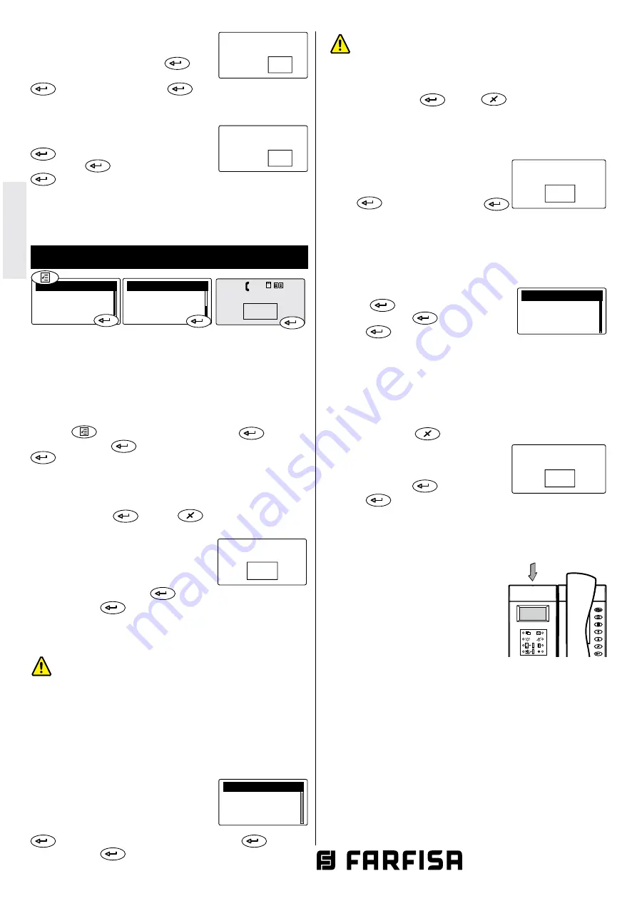
Reset
In addition to Restart command in the “Device Manager” menu,
it is possible to perform a “hard restart” using the button on
the top of the switchboard. To restart
the switchboard press and hold the
button for a few seconds, using a thin
object and taking care not to apply
excessive pressure the switchboard
will reboot without any changes or
data loss.
Software updating
By memory card it is possible to load in the switchboard
memory new software available by contacting the Farfisa
technical service.
To upgrade the software release act as follows:
- load the new software release into a memory card;
- insert the memory card with a maximum capacity of 2 GB
in the proper socket located on the bottom of switchboard;
- restart via the menu or the restart button. Switchboard
will reboot loading the new software version in a few
seconds without losing any data or settings previously
stored.
Delete List
NO
YES
- Administrator
User
PDX Type
Programming block PDX
0
Programming A1
destination address
255
A
J
T
G
P
W
D
M
B
K
U
H
Q
X
E
N
C
L
V
I
R
Y
S
Z
F
O
1
4
7
2
5
8
0
3
6
9