background image

28

75036155 - KJ46 - rev 00 - ( 06-2022 )

KJ 46

GB

F

I

0

1

0.5

MPa

0

0.5

MPa

-

+


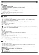
REGOLAZIONE MECCANICA DELLA CORSA

 (Tramite ghiera di regolazione sul cannotto porta testina) (fig. 

f8 - f9

).

Per l'utilizzo della rivettatrice con la regolazione meccanica della corsa, occorre avvitare completamente il regolatore di pressione (

M

) sul fondello e bloccarlo tramite l’apposito 

dado (

X

). Accertarsi che la pressione massima in ingresso sulla macchina sia di 

7

 bar. 

Togliere l'alimentazione dell'aria compressa, smontare testina (

B

), ghiera di bloccaggio (

C

) e protezione (

U

) per accedere alla ghiera di regolazione corsa (

S

). 

Regolare la macchina alla minima corsa, ruotando completamente la ghiera di regolazione corsa (

S

) nel senso indicato dal simbolo “ 

 ”. In queste condizioni  l'indice di 

riscontro (

S

), inciso sulla ghiera, risulterà posizionato poco oltre la metà dell’asola sul cannotto lato motore.

Rimontare  testina (

B

) e ghiera di bloccaggio (

C

). Attivare l'alimentazione dell'aria compressa.

Avvitare un inserto delle dimensioni desiderate sul tirante ed eseguire le operazioni preliminari come riportato a 

pag.20

 . Applicare l’inserto sul materiale e verificare il 

serraggio. Regolare gradualmente la corsa della rivettatrice, mediante la rotazione della ghiera di regolazione corsa (

S

), fino ad ottenere il serraggio ottimale, considerando che, 

all’aumentare della corsa (rotazione della ghiera (

S

) nel senso indicato dal simbolo “

+

”) aumenta la deformazione dell’inserto con conseguente aumento dell’azione di serraggio.

Eseguite le regolazioni disattivare l’alimentazione dell’aria compressa e rimontare la protezione (

U

) per evitare accidentali variazione alla regolazione impostata.


RÉGLAGE MÉCANIQUE DE LA COURSE

 (au moyen de la bague de réglage sur le manchon porte-tête)


(fig. 

f8 - f9

)

.

Pour utiliser la riveteuse avec le réglage mécanique de la course, il faut visser complètement le régulateur de pression (

M

) sur le fond et le bloquer avec l'écrou approprié (

X

). 

Vérifier que la pression maximale à l’entrée de la machine est de 

7

 bars. 

Couper l'alimentation en air comprimé, démonter la tête (

B

), la bague de verrouillage (

C

) et la protection (

U

) pour accéder à la bague de réglage de la course (

S

). 

Régler la machine sur la course minimale en tournant complètement la bague de réglage de la course (

S

) dans le sens indiqué par le symbole «  - ». Dans cette condition, 

l'index de butée (

T

), gravé sur la bague, sera positionné juste au-delà du milieu de la fente sur le manchon côté moteur.

Réinstaller la tête (

B

) et la bague de verrouillage(

C

). Activer l'alimentation en air comprimé.

Visser un insert de la taille souhaitée sur le tirant et effectuer les opérations préliminaires décrites à la 

page 20

. Appliquer l'insert sur le matériau et vérifier le serrage. Régler 

progressivement la course de la riveteuse, au moyen de la bague de réglage de la course (

S

), jusqu'à obtenir le serrage optimal, en tenant compte du fait qu'au fur et à mesure 

que la course augmente (rotation de la bague (

S

) dans le sens indiqué par le symbole « 

+

 »), la déformation de l'insert augmente, avec une augmentation conséquente du serrage.

Une fois les réglages effectués, couper l'alimentation en air comprimé et réinstaller la protection (

U

) pour éviter toute modification accidentelle du réglage.


MECHANICAL STROKE ADJUSTMENT 

(Via adjustment ring nut on head holder sleeve)

 (

fig

. f8 - f9

).

To use the riveting tool with mechanical stroke adjustment, the pressure regulator (

M

) must be screwed completely on to the end cap and secured with the nut (

X

). Make sure 

that the maximum inlet pressure on the machine is 

7

 bar. 

Remove compressed air supply, remove head (

B

), locking ring (

C

) and protection (

U

) to access the stroke adjustment ring (

S

). 

Adjust the machine to the minimum stroke by fully turning the stroke adjustment ring (

S

) in the direction indicated by the symbol " - ". In this condition, the striker index (

T

), 

engraved on the ring nut, will be positioned just beyond the middle of the slot on the motor side sleeve.

Refit the head (

B

) and locking ring nut (

C

). Switch on the compressed air supply.

Screw an insert of the desired size onto the tie rod and carry out the preliminary operations as described on 

page 20

. Apply the insert to the material and check the tightness. 

Gradually adjust the stroke of the riveting tool, by turning the stroke adjustment ring nut (

S

), until the optimum tightening action is obtained, considering that, as the stroke 

increases (turning the ring nut (

S

) in the direction indicated by the symbol "

+

") the deformation of the insert increases, with a consequent increase in the tightening action.

After the adjustments have been made, switch off the compressed air supply and refit the guard (

U

) to prevent accidental changes to the set setting.

M

V

X

C

U

S

T

B

-

+

MAX

0,7


MPa


7


bar

f8

f9

Summary of Contents for KJ 46

Page 1: ...D EMPLOI PIECES DETACHEES BERSETZUNG VON ORIGINALANLEITUNGEN PNEUMATISCH HYDRAULISCHES NIETWERKZEUG F R BLINDNIETMUTTERN M4 M10 BEDIENUNGSANLEITUNG ERSATZTEILE TRADUCCION DE LAS ISTRUCCIONES ORIGINAL...

Page 2: ...P THE OIL DYNAMIC CIRCUIT 34 MAINTENANCE 36 DISPOSAL OF THE RIVETING TOOL 36 TROUBLE SHOOTING 39 SPARE PARTS 48 D CLARATION DE CONFORMIT 4 GARANTIE 5 INSTRUCTIONS ET MESURES DE SECURITE 6 IDENTIFICATI...

Page 3: ...POWIETRZEM 19 WST PNE CZYNNO CI PRZED URUCHOMIENIEM 21 REgULACjAZESPO UTRZPIE g OWICA 21 U YTKOWANIE NITOWNICY 23 REgULACjA SI Y ZACI gANIA ZA POMOC REgULATORA CI NIENIA I MANOMETRU 25 MECHANICZNA REg...

Page 4: ...er Berechtigte zur Bildung der technische Brosch re ist Massimo Generali bei der Firma Far S r l mit Sitz in Via giovanni XXIII 2 Fraz Quarto Inferiore 40057 granarolo Emilia Bologna Italy La firmatar...

Page 5: ...ertragsh ndlererworbenund ausschlie lichzudenZweckenverwendet wird f r die es konzipiert wurde Die Garantie wird ung ltig wenn das Ger t nicht in Einklang mit den Anweisungen in der Betriebs und Wartu...

Page 6: ...en Die Firma FAR s r l haftet nicht f r durch defekte Teile verursachte Sch den sofern diese auf die Mi achtung der o g Vorschrift zur ckzuf hrensind Richtlinie85 374 EWG DieListederReparaturservicesi...

Page 7: ...ci zamiennych firma FAR nie ponosi adnej odpowiedzialno ci za wypadki powsta e na skutek niew a ciwego u ycia narz dzia Dyrektywa UE 85 374 Lista punkt w serwisowych jest dost pna na naszej stronie i...

Page 8: ...orrect size to be used Do not carry the connected tool by pulling the hose The hole must be far from any heating sources or from cutting parts Keep the tools in good conditions do not remove either sa...

Page 9: ...ss o ponderada A seja superior ao limite de seguran a de 70 dB A usar adequados equipamentos de prote o individual do ouvido tamp es diminui o do tempo de exposi o di ria etc Manter a bancada e ou a r...

Page 10: ...VETER L outil de pose KJ 46 est identifi par un marquage indiquant raison sociale et adresse du fabricant d signation de l outil de pose marquage CE En cas de recours au service apr s vente il faut to...

Page 11: ...maszyny i oznakowaniem CE Korzystaj c z pomocy technicznej nale y zawsze poda dane znajduj ce si na oznaczeniu KJ 46 CE Ragione sociale e indirizzo del fabbricante Company name and address Raison soc...

Page 12: ...dimensions et le poids du pistolet en la rendant tr s maniable Les risques de fuites du syst me ol odynamique sont limin s par l utilisation de joints haute r sistance ALLGEMEINES UND ANWENDUNGSBEREIC...

Page 13: ...nacznie zmniejszy y ci ar narz dzia i polepszy y jego ergonomi Ponadto udoskonalony system uszczelniaczy eliminuje mo liwo spadku mocy zacisku M4 M10 1 2 KJ46 KJ 46 A ferramenta destina se apenas a se...

Page 14: ...Manometro X Dado bloccaggio regolatore di pressione A Threaded tie rod B Head C Ring nut clamping head D Control push button E Compressed air connection F Pressure control valve G Protection bottom H...

Page 15: ...de tope U Protecci n V Man metro X Tuerca de bloqueo del regulador de presi n A Tirante roscado B Cabe a C Virola de bloqueio da cabe a D Bot o de comando E Conex o do ar comprimido F V lvula de contr...

Page 16: ...2 5 m s2 A weighted emission sound pressure level 74 dBA Peak C weighted instantaneous sound pressure 130 dBC A Weighted sound power 86 dBA DONN ES TECHNIQUES Pression d utilization 6 7 BAR Diam tre...

Page 17: ...Nl nl litry przy 20 C ci nienie atmosferyczne Si a maksymalna 6 BAR 24000 N Skok 7 mm Waga 2 540 Kg Temperatura robocza 5 st C 50 St C Przyspieszenie r ka rami 2 5 m s2 Ci nienie akustyczne emisji sk...

Page 18: ...er of the air entry valve Q to feed the tool AIR FEED fig f1 The compressed air system must be provided with air cleaners and condensation drains and must guarantee that the air supplied to the feeder...

Page 19: ...muss man kontrollieren dass der Druckluftversorgung der Nietmaschine dem unter technischen Daten auf Seite 16 dieser Anleitung angegebenen Druckwert entspricht Um das Werkzeug zu speisen den Steuerkol...

Page 20: ...assembled on this riveting tool corresponds to a M8 thread Before using the riveting tool and after each change of format the stroke power must be adjusted according to the size type of insert and th...

Page 21: ...illar una tuerca remachable de la longitud querida sobre el tirante fileteado manualmente hasta que la cabeza de la tuerca toque la cabeza B de la remachadora La cabeza es ajustada correctamente si el...

Page 22: ...aded inserts by choosing between two different methods of use 1 Power setting via pressure regulator and pressure gauge on the bottom of the riveting tool 2 Mechanical stroke adjustment via adjustment...

Page 23: ...aplicaci n de remaches mediante el ajuste de potencia antes de utilizarla consulte el cap tulo titulado AJUSTE DE LA POTENCIA A TRAV S DE UN REGULADOR DE PRESI N Y UN MAN METRO ATEN O N o absolutament...

Page 24: ...use fonctionne mais elle incapable d effectuer la course et de serrer l insert En augmentant progressivement la puissance via le r gulateur de pression M la d formation de l insert est progressivement...

Page 25: ...les y campo de aplicaci n de la m quina no bajar del ajuste m nimo le do en el man metro V suministrado en la parte inferior de 1 bar y no superar el ajuste m ximo de 5 5 bar Sigue REGULA O DA POT NCI...

Page 26: ...vel talonnage de la pression Le manom tre situ dans le fond n est qu un instrument indicatif de lecture de la pression et ne doit pas remplacer lors du r glage talonnage de la machine la v rification...

Page 27: ...s de 0 5 bar colocando el puntero rojo de referencia en el centro de los espacios entre una muesca y la siguiente REGULA O DA POT NCIA PELO REGULADOR DE PRESS O E MAN METRO DEFINI ES DE F BRICA fig f7...

Page 28: ...ourse S dans le sens indiqu par le symbole Dans cette condition l index de but e T grav sur la bague sera positionn juste au del du milieu de la fente sur le manchon c t moteur R installer la t te B e...

Page 29: ...ci n de apriete Una vez realizados los ajustes desconecte el suministro de aire comprimido y vuelva a colocar la protecci n U para evitar cambios accidentales en el ajuste MECHANICZNA REGULACJA SKOKU...

Page 30: ...is completely pulled and push the button P to release the tie rod fig f11 Insufficient deformation fig f12 1 the insert could rotate inside the housing compromising its use and resistance Excessive d...

Page 31: ...ownic do pracy reguluj c si zaci gania lub reguluj c mechanicznie skok roboczy jak pokazano na stronach 24 29 Na gwintowany trzpie A nak adamy nitonakr tk pod wp ywem lekkiego nacisku trzpie wkr ci si...

Page 32: ...upling release plug R is in phase with the slot on the sleeve Make the pin supplied pass through the pertinent service hole and apply a light pressure on the head inwards in order to dechuck the tie r...

Page 33: ...a virola que se afloj anteriormente ACHTUNG Die obenstehenden schritte sind bei nicht gespeister maschine durchzuf hren ATENCI N Las operaciones susodichas tienen que ser efectuadas con la m quina par...

Page 34: ...riveting tool in a vertical position unscrew and close the oil container Y and the plug I checking the soundness of the hermetic washer and repeat all the adjustments for placing the insert as indica...

Page 35: ...NG Stellen Sie vor dem Trennen des Druckluftrohres der Nietmaschine sicher dass dieses nicht unter Druck steht Es empfiehlt sich l HLP 32 cSt oder hnliches zu verwenden LLENADO DE ACEITE DEL CIRCUITO...

Page 36: ...luminium plastic material etc Then proceed to scrap the materials in accordance with current laws ENTRETIEN Entretien quotidien s assurer que le tirant filet n est pas endommag contr ler le syst me d...

Page 37: ...przewod w powietrza upewni si ze ci nienie zasilaj ce nie przekracza 7 bar Konserwacja tygodniowa sprawdzamy poziom oleju rys f18 Przegl d serwisowy Zalecamy gruntowny przegl d narz dzia po 300 000 cy...

Page 38: ...o del regolatore di pressione Rivolgersi al centro assistenza Danneggiamento Valvola di scarico rapido Rivolgersi al centro assistenza Danneggiamento guarnizione manometro Rivolgersi al centro assiste...

Page 39: ...essure regulator damage malfunctioning Contact the service center Quick exhaust Valve Damage Contact the service center Pressure gauge damage Rivolgersi al centro assistenza Thepr essureg augedo es no...

Page 40: ...onnement du r gulateur de pression Contacter le service apr s vente SAV Dommage Soupape d chappement rapide Contacter le service apr s vente SAV Dommage au joint du manom tre Contacter le service apr...

Page 41: ...des Druckreglers Wenden Sie sich an das Service Center Besch digung Schnellauslassventil Wenden Sie sich an das Service Center Besch digung der Dichtung des Manometers Wenden Sie sich an das Service C...

Page 42: ...en contacto con el servicio tecnico Da o de la v lvula de descarga r pida P ngase en contacto con el servicio tecnico Da os en la junta del man metro P ngase en contacto con el servicio tecnico E lma...

Page 43: ...regulatora ci nienia Skontaktowa si z centrum obs ugi klienta Uszkodzenie zaworu szybkiego spustu Skontaktowa si z centrum obs ugi klienta Uszkodzenie uszczelki manometru Skontaktowa si z centrum obs...

Page 44: ...44 75036155 KJ46 rev 00 06 2022 KJ 46 RUS...

Page 45: ...to com a assist ncia t cnica Danos V lvula de escape r pido Entre em contato com a assist ncia t cnica Danos no selo do man metro Entre em contato com a assist ncia t cnica Oman metron ofunci ona Dano...

Page 46: ...04 71346776 1 Tirante M10 05 71346789 1 Testina M6 06 71346774 1 Tirante M6 07 71346788 1 Testina M5 08 71346773 1 Tirante M5 09 71346787 1 Testina M4 10 71346772 1 Tirante M4 11 710876 1 Spina disinn...

Page 47: ...ne OR 2 129 A 23AP 710823 2 Gabbia AP 24 71346470 1 Silenziatore 25 72000522 1 Cilindro pneumatico 26 71346718 1 Guida stelo 27 71346719 1 Tubo 8 x 7 28 71346717 1 Stelo 29 71346716 1 Raccordo 30 7134...

Page 48: ...asket OR 2 107 4 KITQ 74000122 Oil dynamic kit TAB 14Q 711722 1 Gasket B 094063 B NEI 2 22Q 713389 1 Gasket 157118 B NEO 2 36Q 71346560 2 Gasket TTS 16x21x5 7 4 KIT It indicates that the part is sold...

Page 49: ...1 Gasket OR 2 129 A 23AP 710823 2 Cage AP 24 71346470 1 Silencer 25 72000522 1 Cilindro pneumatico 26 71346718 1 Rod guide 27 71346719 1 Tube 8 x 7 28 71346717 1 Rod 29 71346716 1 Connector 30 713467...

Page 50: ...22 Q t Kit hydraulique Tav 14Q 711722 1 Joint B 094063 B NEI 2 22Q 713389 1 Joint 157118 B NEO 2 36Q 71346560 2 Joint TTS 16x21x5 7 4 KIT Indique que la pi ce est vendue dans des KITS compos s de dive...

Page 51: ...129 A 23AP 710823 2 Cage AP 24 71346470 1 Silencieur 25 72000522 1 Cylindre pneumatique 26 71346718 1 Guide tige 27 71346719 1 Tuyau 8 x 7 28 71346717 1 Tige 29 71346716 1 Raccord 30 71346715 1 Ecrou...

Page 52: ...775 1 Gewindedorn M8 03 71346791 1 Mundst ck M 10 04 71346776 1 Gewindedorn M 10 05 71346789 1 Mundst ck M 6 06 71346774 1 Gewindedorn M6 07 71346788 1 Mundst ck M 5 08 71346773 1 Gewindedorn M5 09 71...

Page 53: ...8 73 A 07A 71C00356 1 Dichtung OR 1 78 x 7 66 A 08 72000363 1 K rper 09 71C01022 1 Verschluss 1 4 10 711259 1 Dienstst psel 11 712117 1 Unterlegscheibe Federstop 12 710841 1 Ventil 13A 710916 1 Dicht...

Page 54: ...DESCRIPCI N 01 71346790 1 Cabeza M8 02 71346775 1 Tirante M8 03 71346791 1 Cabeza M10 04 71346776 1 Tirante M10 05 71346789 1 Cabeza M6 06 71346774 1 Tirante M6 07 71346788 1 Cabeza M5 08 71346773 1 T...

Page 55: ...rola 1 4 06A 71C00355 1 Junto OR 1 78 x 8 73 A 07A 71C00356 1 Junto OR 1 78 x 7 66 A 08 72000363 1 Cuerpo 09 71C01022 1 Tap n 1 4 10 711259 1 Tap n de servicio 11 712117 1 Arandela bloqueo muelle 12 7...

Page 56: ...M8 02 71346775 1 Korek M8 03 71346791 1 Kolnierza M10 04 71346776 1 Korek M10 05 71346789 1 Kolnierza M6 06 71346774 1 Korek M6 07 71346788 1 Kolnierza M5 08 71346773 1 Korek M5 09 71346787 1 Kolnierz...

Page 57: ...00355 1 Uszczelka OR 1 78 x 8 73 A 07A 71C00356 1 Uszczelka OR 1 78 x 7 66 A 08 72000363 1 Korpus 09 71C01022 1 Korek 1 4 10 711259 1 Korek serwisowy 11 712117 1 Podk adka zatrzymania spr yny 12 71084...

Page 58: ...1 M10 05 71346789 1 M6 06 71346774 1 M6 07 71346788 1 M5 08 71346773 1 M5 09 71346787 1 M4 10 71346772 1 M4 11 710876 1 12 72A00053 1 13 712225 1 4 mm KIT KITA 74000121 Zestaw uszczelek 04A 711337 1...

Page 59: ...71C00355 1 OR 1 78 x 8 73 A 07A 71C00356 1 OR 1 78 x 7 66 A 08 72000363 1 09 71C01022 1 1 4 10 711259 1 11 712117 1 12 710841 1 13A 710916 1 OR 2 015 A 14A 710528 1 OR 008 A 15A 710258 1 OR 5 612 A 16...

Page 60: ...2 71346775 1 Tirante M8 03 71346791 1 Cabe ote M10 04 71346776 1 Tirante M10 05 71346789 1 Cabe ote M6 06 71346774 1 Tirante M6 07 71346788 1 Cabe ote M5 08 71346773 1 Tirante M5 09 71346787 1 Cabe ot...

Page 61: ...0355 1 O ring OR 1 78 x 8 73 A 07A 71C00356 1 O ring OR 1 78 x 7 66 A 08 72000363 1 Corpo 09 71C01022 1 Tampa 182 10 711259 1 Taco 11 712117 1 Anilha retentora da mola 12 710841 1 Espoleta 13A 710916...

Page 62: ...06 2022 KJ 46 KJ 46 13 12 11 KITA KIT Q 3 4 1 2 5 6 7 8 9 10 Tav 02 Tav 03 Tav 04 PARTI DI RICAMBIO SPARE PARTS PIECES DETACHEES ERSATZTEILE PIEZAS DE REPUESTO CZ CIZAMIENNE PE AS SOBRESSALENTES Tav...

Page 63: ...12 KIT C KIT B KIT F KIT E KIT G 24 22 Q 14 Q 16 A 27 A 26 A 23 A 17 A 20 A 19 A 37 A 36 A 31 30 A 29 35 G 33 29 34 G 35G x1 34G x1 1 2 3 4 A 5 KJ 46 7 Tav 02 8 1 6 PARTI DI RICAMBIO SPARE PARTS PIECE...

Page 64: ...IT M KIT I 1 KIT A 2 3 1 KIT A 2 4 KIT H 5 6 KIT I KIT L KIT M 9 A 7 A 11 A 10 A M M M M 8 A Tav 03 KJ 46 PARTI DI RICAMBIO SPARE PARTS PIECES DETACHEES ERSATZTEILE PIEZAS DE REPUESTO CZ CIZAMIENNE PE...

Page 65: ...0 A 30 31 42 33 47 48 34 41 A 28 29 39 A 41 A 40 A 22 A 1 2 3 KIT R KIT R KIT P KIT N KIT S KIT O 41 A 43 A 44 A 46 A 45 A 23 A KJ 46 KJ 46 Tav 04 KIT N KIT P 5 4 A 6 A 7 A 32 PARTI DI RICAMBIO SPARE...

Page 66: ...6155 KJ46 rev 00 06 2022 KJ 46 1 6 11 8 12 13 14 7 8 9 10 2 3 4 5 PARTI DI RICAMBIO SPARE PARTS PIECES DETACHEES ERSATZTEILE PIEZAS DE REPUESTO CZ CIZAMIENNE PE AS SOBRESSALENTES Tav 5 5 Tab 5 5 Taf 5...

Page 67: ......

Page 68: ...p www far bo it A lista de centros de servi o est dispon vel no nosso site Web http www far bo it Organiza o SISTEMI DI FISSAGGIO FASTENING SYSTEMS SYSTEMES DE FIXATION VERBINDUNGSSYSTEME SISTEMAS DE...

Reviews: