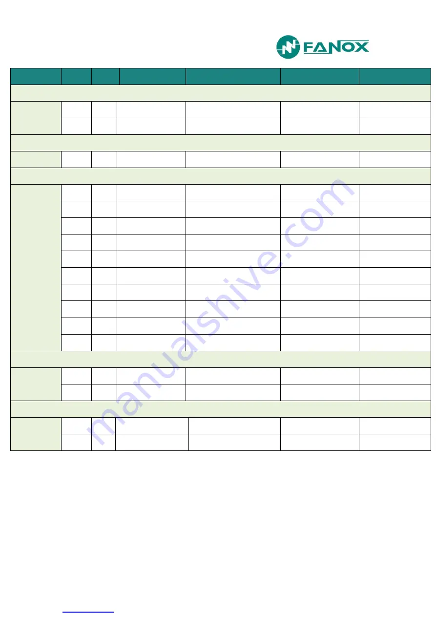
FANOX SIL-V User Manual Download Page 62


www.fanox.com


Rev.10   


62/212 

Group 

Bit 

Event 

Status 

Event 

Cause 

Measurement 

Level 2: Rate of change of frequency 

81R_2 

Bit-04 

01 

81R_2 Pickup 

81R_2 Pickup 

Activation/Deactivation 

Frequency 

Bit-12 

02 

81R_2 Trip 

81R_2 Trip 

Activation/Deactivation 

Frequency 

Out of step (vector shift) 

78 

Bit-12 

02 

48 Trip 

78 Trip 

Activation/Deactivation 

Frequency 

Recloser 

79 

Bit-00 

01 

79 Standby 

79 Standby 

Activation/Deactivation 

Bit-01 

02 

79 Reclosing time 

79 Reclosing time 

Activation 

Auto-reclosing No. 

Bit-02 

03 

79 Open 

79 Open 

Activation 

Reclose No. 

Bit-03 

04 

79 Hold time 

79 Hold time 

Activation 

Auto-reclosing No. 

Bit-04 

05 

79 Closing time 

79 Closing time 

Activation 

Auto-reclosing No. 

Bit-05 

06 

79 Reset time 

79 Reset time. 

Activation 

Reclose No. 

Bit-06 

07 

79 Lockout 

79 Lockout 

Activation/Deactivation 

Reclose No. 

Bit-07 

08 

79 Safety time 

79 Safety time 

Activation 

Reclose No. 

Bit-08 

09 

79 Final opening time 

79 Final opening time 

Activation 

Bit-09 

79 Enabled 

Breaker failure 

BF 

Bit-04 

01 

BF Pickup 

BF Pickup 

Activation/Deactivation 

Bit-12 

02 

BF Trip 

BF Trip 

Activation/Deactivation 

Trip circuit supervision 

74TCS 

Bit-04 

01 

74TCS Pickup 

74TCS Pickup 

Activation/Deactivation 

Bit-12 

02 

74TCS Alarm 

74TCS Alarm 

Activation/Deactivation 


Summary of Contents for SIL-V

Page 1: ...EN_FANOXTD_MANU_SIL_Voltagefrequency_SILV_R010 Docx USER S MANUAL SER S MANUAL SIL V Voltage frequency and synchronism protection relay...

Page 2: ...Definite time phase overvoltage 28 4 4 Function 59N Definite time neutral overvoltage 28 4 5 Function 47 Definite time negative sequence overvoltage 29 4 6 Function V t Rate of change of voltage 29 4...

Page 3: ...hronisation 81 5 15 Test program 82 5 16 Power supply 83 6 TECHNICAL SPECIFICATIONS AND STANDARD 84 6 1 Technical specifications 84 6 2 Standards 89 7 COMMUNICATION AND HMI 92 7 1 Local communication...

Page 4: ...ds map 175 8 2 5 Examples of Mosdbus frames 176 9 IEC 60870 5 103 PROTOCOL 177 9 1 Physical layer 177 9 2 Application layer 177 10 IEC 61850 PROTOCOL 185 10 1 Data model 185 10 2 Services 190 10 3 Ope...

Page 5: ...ectronic components can cause serious damage to electronic circuits It is possible that this damage may not be detected straight away but the electronic circuit eliability and life will be reduced Thi...

Page 6: ...est possible cable As well as guaranteeing safety for the personnel this connection allows high frequency noise to be evacuated directly to earth The following checks must be performed before the equi...

Page 7: ...www fanox com Rev 10 7 212 2 DIMENSIONS AND CONNECTION DIAGRAMS 2 1 Equipment front view...

Page 8: ...www fanox com Rev 10 8 212 2 2 Equipment dimensions...

Page 9: ...www fanox com Rev 10 9 212 2 3 Cut out pattern...

Page 10: ...mers 3 VT configuration phase neutral 3 VT configuration phase neutral residual voltage 3VT configuration phase phase residual voltage 2VT configuration phase phase residual voltage Connecting the rel...

Page 11: ...www fanox com Rev 10 11 212 3 VT configuration phase neutral...

Page 12: ...www fanox com Rev 10 12 212 3 VT configuration phase neutral residual voltage SILVxxxx0xxxxx...

Page 13: ...www fanox com Rev 10 13 212 3 VT configuration phase neutral busbar voltage SILVxxxx2xxxxx...

Page 14: ...www fanox com Rev 10 14 212 3VT configuration phase phase residual voltage...

Page 15: ...www fanox com Rev 10 15 212 2VT configuration phase phase residual voltage...

Page 16: ...www fanox com Rev 10 16 212 Connecting the relay directly to Low Voltage line SILVxxxx0xxxxx and SILVxxxx2xxxxx Phase to neutral configuration 250 480 V...

Page 17: ...www fanox com Rev 10 17 212 2 5 Terminals...

Page 18: ...age D8 Digital input 5 A1 A2 Phase A voltage measurement D9 Digital input 6 A3 A4 Phase B voltage measurement D10 Common digital inputs 3 4 5 and 6 A5 A6 Phase C voltage measurement D11 Digital 1 comm...

Page 19: ...the accumulated amps It generates an indication if these are excessive it determines whether or not an Opening fault has occurred and allows the circuit breaker close and open commands from the HMI wi...

Page 20: ...necting directly to the low voltage line in this case voltage transformers are not required It has two communications ports one front port RS232 and one rear port The RS232 port allows a PC to be conn...

Page 21: ...ain connected causing a safety hazard within the network Automatic reconnection of the generator to the network may occur causing damage to the generator and to the network SIL V protection detects th...

Page 22: ...N1 59N2 V T Rate of change of Voltage 1 74TCS Trip circuit supervision 1 78 Out of step vector shift 1 81O U Overfrequency Underfrequency 4 81_1 81_2 81_3 81_4 81R Rate of change of frequency 2 81R_1...

Page 23: ...spect to the time dVB dt Rate of change of phase C voltage respect to the time dVC dt Rate of change of frequency respect to time df dt Line frequency Bar frequency Depending on model Frequency differ...

Page 24: ...with configurable passwords HMI LCD 20x2 6 keys 1 reset button 2 keys for 52 control 1 key for 79 Lock Unlock LED Indicators 8 leds All configurable Power Supply Auxiliary voltage 24 220 Vdc 48 230 V...

Page 25: ...www fanox com Rev 10 25 212 3 3 Functional Diagram...

Page 26: ...Vdc 48 230 Vac 0 2 Additional Functions 25 A B C D Communications RS232 Modbus RTU RS485 Modbus RTU or IEC 60870 5 103 RS232 Modbus RTU RJ45 IEC 61850 RS232 Modbus RTU RJ45 DNP3 0 TCP IP RS232 Modbus...

Page 27: ...me is adjusted with reset time parameter The accuracy of the operating time is the adjusted time 30ms or 0 5 greater of both 4 2 Function 27V1 Definite time positive sequence undervoltage This protect...

Page 28: ...ing time is the adjusted time 30ms or 0 5 greater of both 4 4 Function 59N Definite time neutral overvoltage There are two independent neutral overvoltage functions This protection function is adjuste...

Page 29: ...ltage such that if the negative sequence voltage exceeds the adjusted value for a period of time equal to or higher than the pre established value the protection function actuates trips and does not r...

Page 30: ...e reset time setting The frequency measurement is done from the voltage of phase B It takes a minimum of 45 volts at this stage for 81 functions to be operational If the measured phase voltage is less...

Page 31: ...If decrement type is selected and the frequency decreases at a higher rate than the value specified by activation level setting during the operating time the function trips The function activates at 1...

Page 32: ...ately The accuracy is 5 4 10 Function 52 Circuit Breaker monitoring This function allows the status of the circuit breaker to be monitored and preventive maintenance to be performed for which the foll...

Page 33: ...unter that measures the number of openings exceeds the Maximum number of openings setting Repeated Trips Activated the number of openings exceeds the setting in Maximum repeated openings for the time...

Page 34: ...nputs These physical inputs are then assigned to the corresponding logical inputs the circuit breaker 52a contact to the 52a logical signal and the circuit breaker 52b contact to the 52b logical signa...

Page 35: ...pment must be in TELECONTROL mode see the telecontrol section For the commands to have an effect they should be assigned to the corresponding outputs The Open circuit breaker and Close circuit breaker...

Page 36: ...s reset when the BF init status has been reset There is a BF init logical signal to start the open fault from an external protection The BF init is configurable by user The default configuration is sh...

Page 37: ...pecific Operating time that can be set Apart from these times a further three times must be set Hold times This is the time the reclosing device waits for an external condition for closure Replacement...

Page 38: ...locks the recloser and the other locks it Via protocol This is performed via any means of communication This is carried out as if it were a control and the normal conditions of any control must be me...

Page 39: ...me Safety Open Manual Time 52 Open Reclose Init 79 Init Input Configurable Init N Max Number Shots TimeOut 52 Close Wait Reclose Condition TimeOut Reclose Condition Input No Hold Time TimeOut TimeOut...

Page 40: ...s Manual or remote control closing of the circuit breaker In this case it shall switch to safety time If during this time there is a trip it shall revert to Lockout Unlocking of the recloser Via a com...

Page 41: ...0 1 V 50 0 Voltage supervision time 0 02 300 00 0 01 s 3 00 Line Bar voltage difference 4 0 50 0 0 1 V 8 0 Line Bar phase difference 2 0 90 0 0 1 2 0 Line Bar frequency difference 0 06 10 00 0 01 Hz 0...

Page 42: ...line and bar Transitions from dead to live and vice versa are timed with a user adjustable time During the transition the line or bar is in undefined state At such moments as seen in the logical diag...

Page 43: ...an example where the manual close is desired when there is synchronism condition or the line and the bar are dead DLDB CONFIGURATION Manual closure init logical signal one of the commands of close br...

Page 44: ...hronism function It is also necessary to permit the hold permission setting The settings of recloser when there is synchronism are shown below CONFIGURATION 79 Init logical signal General trip 79 Enab...

Page 45: ...P N Vr 3VT P P Vr 3VT P P Vbb 2VTs P P Vr 2 Modbus RTU or IEC60870 5 103 only in SILVxxxxxA E I xxxx models Remote communication parameters depend on model protocol options IEC60870 5 103 or Modbus R...

Page 46: ...dress of front port and address and speed of rear ports see Communications Serial number is a read only setting The rest of the settings can be changed either from the HMI or through communications An...

Page 47: ...ach phase dVA dt dVB dt dVC dt Rate of change of frequency df dt Phase B line frequency Phase B bar frequency depending on model Frequency difference between phase B line and phase B bar depending on...

Page 48: ...yed in real time Group Status General General status Trip 50 Hz Trip Block enable Measurement error Ready Change of settings Time and date synchronisation Local Activity Factory Settings Error Eeprom...

Page 49: ...Phase C Pickup 27_1 Pickup 27_1 Phase A trip 27_1 Phase B trip 27_1 Phase C trip 27_1 Trip 27_2 Level 2 phase instantaneous undervoltage 27_2 Phase A Pickup 27_2 Phase B Pickup 27_2 Phase C Pickup 27...

Page 50: ...Phase C trip 59_1 Trip 59_2 Level 2 phase instantaneous overvoltage 59_2hase A Pickup 59_2 Phase B Pickup 59_2 Phase C Pickup 59_2 Pickup 59_2 Phase A trip 59_2 Phase B trip 59_2 Phase C trip 59_2 Tr...

Page 51: ...81O U_1 Level 1 Over Underfrequency 81_1 Pickup 81_1 Trip 81O U_2 Level 2 Over Underfrequency 81_2 Pickup 81_2 Trip 81O U_3 Level 3 Over Underfrequency 81_3 Pickup 81_3 Trip 81O U_4 Level 4 Over Unde...

Page 52: ...2 Closing fault 52 Excessive openings 52 Excessive openings in a time window 52 a Status 52 b Status Manual close BF Breaker failure BF Pickup BF Trip 74TCS Trip circuit supervision 74TCS Pickup 74TCS...

Page 53: ...lived bar LLDB Lived line dead bar LLLB Lived line lived bar Module difference Frequency difference Phase difference Inputs Digital Inputs Input 1 Input 2 Input 3 Input 4 Input 5 Input 6 Outputs Digi...

Page 54: ...le Reset Settings group 1 Settings group 2 79 Init 79 Enable Level lock 79 Pulse lock 79 Pulse unlock 79 Continuity coil A Continuity coil B Logical signal 1 Logical signal 2 Local Local communication...

Page 55: ...nd 79 a bit is assigned to each condition of the automaton so that if the oscillography must be observed the evolution of this automaton can be seen A brief description of the general statuses is give...

Page 56: ...d a corrupt event in the circular buffer This bit is reset by deleting the events from the HMI or by using communications HMI Activity this condition is active if any key has been pressed in the last...

Page 57: ...ents have the following structure Identifier Unique event identifier e g 51_1 4 27V1 PICKUP Value ON Activated OFF Deactivated an event is generated for Activation and deActivation Year Month Day Time...

Page 58: ...Control Activation Deactivation Bit 10 23 Factory Settings Factory Settings Activation Deactivation Bit 11 24 Error Eeprom Error Eeprom Activation Deactivation Bit 12 28 Eeprom changed Eeprom changed...

Page 59: ...it 08 5 27_1 Phase A trip 27_1 Phase A trip Activation Phase A voltage Bit 09 6 27_1 Phase B trip 27_1 Phase B trip Activation Phase B voltage Bit 10 7 27_1 Phase C trip 27_1 Phase C trip Activation P...

Page 60: ...e Bit 11 8 59_1 Trip 59_1 Trip Activation Level 2 Phase instantaneous overvoltage 59_2 Bit 00 1 59_2 Phase A pickup 59_2 Phase A pickup Activation Deactivation Phase A voltage Bit 01 2 59_2 Phase B pi...

Page 61: ...e Bit 10 7 V t Phase C trip V t Phase C trip Activation Voltage difference Bit 11 8 V t Trip V t Trip Activation Voltage difference Level 1 Over Underfrequency 81O U_1 Bit 04 01 81_1 Pickup 81_1 Picku...

Page 62: ...pen Activation Reclose No Bit 03 04 79 Hold time 79 Hold time Activation Auto reclosing No Bit 04 05 79 Closing time 79 Closing time Activation Auto reclosing No Bit 05 06 79 Reset time 79 Reset time...

Page 63: ...ive openings in a time window 52 Excessive openings in a time window Activation Deactivation Bit 11 12 52 a 52 a Activation Deactivation Bit 12 13 52 b 52 b Activation Deactivation Bit 13 14 Manual cl...

Page 64: ...t 4 Activation Deactivation Bit 04 21 Input 5 Input 5 Activation Deactivation Bit 05 22 Input 6 Input 6 Activation Deactivation Outputs Bit 08 01 Output 1 Output 1 Activation Deactivation Bit 09 02 Ou...

Page 65: ...le Activation Deactivation Bit 25 27 Level lock 79 Level lock 79 Activation Deactivation Bit 26 28 Pulse Lock 79 Pulse Lock 79 Activation Deactivation Bit 27 29 Pulse Unlock 79 Pulse Unlock 79 Activat...

Page 66: ...nd identifier Bit 22 07 Telecontrol Telecontrol Activation Command identifier Bit 23 09 Reset Reset Activation Command identifier Local communication Bit 00 Local COM Bit 01 HMI Activity Bit 17 02 Ope...

Page 67: ...aphy i e an oscillography shall always be associated to the fault report The fault end shall depend on whether the recloser is active If the recloser is prohibited when all Pickup ups disappear it is...

Page 68: ...documented in this manual The SICom communications program allows the oscillograph to be downloaded and saved in COMTRADE format IEEE C37 111 1991 The following information is included in each oscill...

Page 69: ...ndby 10 81_4 Trip 40 79 Lockout 11 81R_1 Trip 42 79 Reclose time 12 81R_2 Trip 42 27_1 Pickup 13 27V1 Trip 43 27_2 Pickup 14 47 Trip 44 59_1 Pickup 15 78 Trip 45 59_2 Pickup 16 dV dt Trip 46 59N_1 Pic...

Page 70: ...ed in the equipment while the oscillograph was being generated Shown below is the format of a COMTRADE header file generated by the SICom program HDR COMTRADE Cycles pre fault 3 Total cycles 88 Analog...

Page 71: ...www fanox com Rev 10 71 212 It is possible to visualize the oscillography using SICom software Using SICom software it is possible to save the oscillo as a COMTRADE file...

Page 72: ...received to avoid false signals a 200 ms pulse is generated to be used in the trip output BF init Start of circuit breaker fault through external protection Fault init Oscillography Start Manual close...

Page 73: ...lated to internal binary states which later can be assigned to logical signal to get a specific operation Physical outputs are the real outputs of the Device SIL V has 4 outputs and 8 configurable led...

Page 74: ...IC CONTROL which can be configured from HMI or from SICom software For each output there is a LOGICAL GATE It can perform a logical operation up to 4 binary states to obtain other binary result In V3...

Page 75: ...is as follows Logical gate selection guide The configured signal will make a pulse of the adjusted milliseconds once the input signal is activated The configured signal waits the adjusted millisecond...

Page 76: ...will be activated till it is externally reset command reset key communications though the input signal drops off The configured signal will make pulses of the adjusted milliseconds while the input si...

Page 77: ...ick up LED 3 OR4 Output 3 LED 4 OR4_LATCH Output 4 LED 5 OR4_LACTH 74TCS Alarm LED 6 OR4_LACTH BF Trip LED 52 OR4 52 Closed LED 79 OR4 79 Standby PHYSICAL OUTPUTS Output 1 OR4 Ready Output 2 OR4 BF Tr...

Page 78: ...ker IEC60870 5 103 close breaker Manual close enable Not configured Reset OR4_PULSE Local reset Remote modbus reset IEC60870 5 103 reset Settings group 1 Not configured Settings group 2 Not configured...

Page 79: ...om local communications or from HMI Output 2 OR4 Local closing Output 2 will be activated when 52 closing command is carried out from local communications or from HMI 52b OR4 Input 2 When physical inp...

Page 80: ...s tables are folded and the relay can operate with one table damaged but not with two damaged There is a WatchDog mechanism between the different main CPUs as well as on the CPUs themselves Loss of ac...

Page 81: ...quipment must be in TELECONTROL mode Operations can be performed from the HMI or from local communications ModBus regardless of whether or not the equipment is in telecontrol 5 13 Telecontrol The equi...

Page 82: ...activated Activated Led 3 activated led 4 Deactivated Led 4 deactivated Activated Led 4 activated led 5 Deactivated Led 5 deactivated Activated Led 5 activated led 6 Deactivated Led 6 deactivated Acti...

Page 83: ...is deactivated by pressing OK Press the C key to exit the test menu The inputs check can be seen in the conditions menu To obtain more detailed information the method for navigating the menus is expl...

Page 84: ...Operating time 0 02 to 300 s step 0 01 s Reset time 0 02 to 300 s step 0 01 s Activation level 100 Deactivation level 105 Temporized deactivation Timing accuracy 30 ms or 0 5 greater of both 59_1 59_...

Page 85: ...ction permission yes no Type Underfrequency or overfrecuency Operating range 45 00 a 65 00 Hz step 0 01 Hz Operating time 0 06 a 300 s step 0 01 s Reset time 0 02 a 300 s step 0 01 s Blocked function...

Page 86: ...o 30 s step 0 01 s Closing time 0 02 to 30 s step 0 01 s Excess repeated openings 1 a 10000 Repeated openings excess time 1 to 300 min BF Function permission yes no Opening failure time 0 02 to 1 00 s...

Page 87: ...s tables Activated by general settings or by inputs RTC Capacitor charge time 10 minutes Operation without auxiliary voltage 72 hours Oscillography 16 samples cycle Oscillo starting configuration 5 re...

Page 88: ...achieve the measurement 40V Accuracy 0 01 Hz Communications LOCAL COMMUNICATION 1 Local port RS232 ModBus RTU REMOTE COMMUNICATION Remote ports with the following options 1 Remote port RS485 ModBus R...

Page 89: ...Hz 2000MHz AM Modulation 80 for 1KHz carrier sinusoidal signal 1 6 Electrical fast transients IEC 60255 26 IEC 61000 4 4 Level 4 Power supply to Earth terminals 4kV Signal and control terminals 2kV Re...

Page 90: ...tial mode for each one of the groups 1kV 2 2 AC or DC dielectric voltage IEC 60255 27 IEC 60255 5 Each group to earth and with rest of the groups in short circuit 2kVac 50Hz 1 minute 2 3 Insulation re...

Page 91: ...to 150Hz 1gn 7 2 Shock IEC 60255 21 2 IEC 60068 21 2 Shock Response Class 1 5gn Shock Withstands Class 1 15gn 7 3 Bump IEC 60255 21 2 IEC 60068 21 2 Bump Class 1 10gn 7 4 Seismic IEC 60255 21 3 IEC 6...

Page 92: ...ort SIL V with 1 port RS485 for ModBus or for IEC60870 5 103 In this case there are 1 RS485 port it is possible to select ModBus RTU protocol or IEC60870 5 103 protocol thanks to the general settings...

Page 93: ...Connection diagram for a RS485 bus SIL V with one RJ45 port for IEC61850 DNP3 0 or IEC60870 5 104 In this case there is one RJ45 port for IEC 61850 protocol for DNP 3 0 protocol or for IEC 60870 5 104...

Page 94: ...e is also a Reset key When Reset is pressed the leds indicators return to their initial position The Reset key can also be used to delete all of the events in the Events menu This is equipped with a s...

Page 95: ...windows net sicom publish htm The link will open the next screen where key install must be pressed The necessary drivers depending on the operative system can be downloaded from this page The update...

Page 96: ...buffer Permission to Execute Commands Permission to Change Configuration Permission to Change Protected Settings 1 YES YES NO NO YES 2 YES YES NO NO NO 3 YES NO YES NO NO 4 YES YES YES NO NO 5 YES YE...

Page 97: ...B C R 0 00 0 00 0 00 0 00 C SILV000C0A12BA 0 00 0 00 0 00 0 00 If any error is detected by the self diagnosis an error message appears in the second line instead of the voltages on the main screen whi...

Page 98: ...e used to increase or decrease the value If an invalid value is entered during the process the C key can be used to delete it The navigation through the menus is described as graphically as possible b...

Page 99: ...08 58828 C FAULT REPORT C OK 07 01 15 12 08 58828 59 1 Pickup C Trip 59 2 07 01 15 10 01 11661 C 7 6 6 Communication parameters and versions Pressing the provides access to the equipment versions Vers...

Page 100: ...ing down the OK key From here press OK to access the components that can be tested OK HOLD TEST MENU y n without protection C SILV000C0A12BA 0 00 0 00 0 00 0 00 OK Set Password 0 C SILV000C0A12BA 0 00...

Page 101: ...nox com Rev 10 101 212 OK Led 2 ACTIVATED Led 3 not activated C OK Led 3 ACTIVATED Led 4 not activated C OK Led 4 ACTIVATED Led 5 not activated C OK Led 5 ACTIVATED Led 6 not activated C OK Led 6 ACTI...

Page 102: ...fanox com Rev 10 102 212 Led 79 not activated C OK Led 79 ACTIVATED Led 52 not activated C OK Led 52 ACTIVATED Output 1 not activated C OK Output 1 ACTIVATED Output 2 not activated C OK Output 2 ACTIV...

Page 103: ...put 3 not activated C OK Output 3 ACTIVATED Output 4 not activated C OK Output 4 ACTIVATED NOTE Be careful when activating the output which is set to trip When the equipment is installed it will open...

Page 104: ...menu is split up into 6 main parts Measurements Status Settings Events Counters Commands Fault report SILV000C0A12BA 0 00 0 00 0 00 0 00 OK MEASUREMENTS C SILV000C0A12BA 0 00 0 00 0 00 0 00 STATES C S...

Page 105: ...er level 7 6 9 Measurements Menu From the standby mode screen press the OK key to access the first line of menus Use the and keys to position the cursor over the MEASUREMENTS screen and press OK Use t...

Page 106: ...w fanox com Rev 10 106 212 3V 0 4 17 0 00 A C V R 5 17 0 00 A C V 2 6 17 0 00 A C V 1 7 17 0 00 A VMin 8 17 0 00 A C VMax 9 17 0 00 A C dVA dt 10 17 0 00 A C dVB dt 11 17 0 00 A C dVC dt 12 17 0 00 A...

Page 107: ...www fanox com Rev 10 107 212 df dt 13 17 0 00 A Lin Frq 14 17 0 00 A C Bar Frq 15 17 0 00 A Frq Diff 16 17 20 C Phs Diff 17 17 20...

Page 108: ...shows whether or not each status is active The message Activation present appears under the name of the group in the status group menus if any of the statuses in that group are active There is a quic...

Page 109: ...ged not activated C Set Date Time not activated C Local Ctrl not activated C FactorySetting not activated C Eeprom error not activated C Eeprom changed not activated C Event error not activated C Rese...

Page 110: ...activated C Phase B pickup not activated C Phase C pickup not activated C Ground pickup not activated C Phase A Trip not activated C Phase B Trip not activated C Phase C Trip not activated C Ground T...

Page 111: ...ivated C Blck Freq Bar not activated C OK Sta 27 1 C STATES OK Phase A Pickup not activated C Sta 27 1 Phase B Pickup not activated C Phase C Pickup not activated C Phase Pickup not activated C Phase...

Page 112: ...e C Trip not activated C Phase Trip not activated C Sta 27 2 C STATES OK Phase A Pickup not activated C Sta 27 2 Phase B Pickup not activated C Phase C Pickup not activated C Phase Pickup not activate...

Page 113: ...212 Phase B Trip not activated C Phase C Trip not activated C Phase Trip not activated C Sta 27V1 C STATES OK Pickup not activated C Sta 27V1 Trip not activated C Sta 59 1 C STATES OK Phase A Pickup...

Page 114: ...activated C Phase C Pickup not activated C Phase Pickup not activated C Phase A Trip not activated C Phase B Trip not activated C Phase C Trip not activated C Phase Trip not activated C Sta 59 2 C ST...

Page 115: ...Phase B Pickup not activated C C Phase C Pickup not activated C OK Phase Pickup not activated C Phase A Trip not activated C Phase B Trip not activated C Phase C Trip not activated C Phase Trip not ac...

Page 116: ...116 212 OK Pickup not activated C Sta 59N 1 Trip not activated C Sta 59N 2 C STATES OK Pickup not activated C Sta 59N 2 Trip not activated C Sta 47 STATES Pickup not activated Sta 47 Trip not activate...

Page 117: ...not activated C Sta V t Phase B Pickup not activated C Phase C Pickup not activated C Phase Pickup not activated C Phase A Trip not activated C Phase B Trip not activated C Phase C Trip not activated...

Page 118: ...212 OK Pickup not activated C Sta 81 1 Trip not activated C Sta 81 2 C STATES OK Pickup not activated C Sta 81 2 Trip not activated C Sta 81 3 C STATES OK Pickup not activated C Sta 81 4 Trip not acti...

Page 119: ...212 OK Pickup not activated C Sta 81 4 Trip not activated C Sta 81R 1 C STATES OK Pickup not activated C Sta 81R 1 Trip not activated Sta 81R 2 C STATES OK Pickup not activated C Sta 81R 2 Trip not a...

Page 120: ...ip not activated C Sta 78 Sta 74TCS C STATES OK Pickup not activated C Sta 74TCS Alarm not activated Sta BF C STATES OK Pickup not activated C Sta BF Trip not activated Sta 79 Lockout C STATES OK Stan...

Page 121: ...lose Time not activated C 79 Is 52 Open not activated C 79 Hold Time not activated C 79 Close Time not activated C 79 Reset Time not activated C 79 Lockout not activated C 79 Security T not activated...

Page 122: ...C STATES OK 52 Startup not activated C Sta 52 52 Error 52 Error not activated C 52 Open not activated C 52 Open Time not activated C 52 Open Error ACTIVATED C 52 Close not activated C 52 Close Time no...

Page 123: ...212 Open Num Alarm ACTIVATED C Too Many Trips not activated C 52A contact not activated C 52B contact not activated C Manual close not activated C Sta 25 C STATES OK Synchrocheck not activated C Sta...

Page 124: ...2 DLLB not activated C LLDB not activated C LLLB not activated C Module diff not activated C Freq diff not activated C Phase diff not activated C Sta INPUTS C STATES OK Input 1 not activated C Sta INP...

Page 125: ...ot activated C Input 4 not activated C Input 5 not activated C Input 6 not activated C Sta OUTPUTS Activated C STATES OK Output 1 ACTIVATED C Sta OUTPUTS Activated Output 2 not activated C Output 3 no...

Page 126: ...212 Sta LEDS Activated C STATES OK Led1 ACTIVATED C Sta LEDS Activated Led2 not activated C Led3 not activated C Led4 not activated C Led5 not activated C Led6 not activated C C Led 52 not activated...

Page 127: ...ated C STATES OK 52a not activated C Sta LOGIC Activated 52b not activated C Ext Trip not activated C BF Init not activated C Fault Init not activated C Manual close Init not activated C Manual close...

Page 128: ...ettingsG1 not activated C SettingsG2 not activated C 79Init not activated C 79 Enable not activated C L Lock 79 not activated C P Lock 79 not activated C P Unlock 79 not activated C 74TCS A not activa...

Page 129: ...ated C Logic Sig2 not activated C Sta LOCAL Activated C STATES OK Local COM not activated C Sta LOCAL Activated HMI Activity ACTIVATED C Open Breaker not activated C Close Breaker not activated C P Lo...

Page 130: ...not activated C Telecontrol not activated C Reset not activated C Sta REMOTE C STATES OK Remote COM not activated C Sta REMOTE Open Breaker not activated C Close Breaker not activated C P Lock 79 not...

Page 131: ...w fanox com Rev 10 131 212 Local Ctrl not activated C Telecontrol not activated C Reset not activated C NOTE REMOTE COM can be ModBus IEC60870 5 103 IEC61850 DNP3 0 or IEC60870 5 104 depending on mode...

Page 132: ...and keys to position the cursor over a settings group and press the OK key to access the settings that belong to this group Use the and keys to move through the different settings The information tha...

Page 133: ...K Set Password 0 C Function Enable NO Set Password 5555 OK Function Enable NO NO Function Enable NO YES OK Function Enable NO YES y n OK SETTING CHANGED Function Enable OK Function Enable YES Tap 10 0...

Page 134: ...212 Reset time 0 20 s Sett 1 27 2 C SETTINGS GEN COM OK Function Enable NO C Sett 1 27 2 Tap 10 00 V C Operating time 5 00 s C Reset time 0 20 s Sett 1 27V1 C SETTINGS GEN COM OK Function Enable NO C...

Page 135: ...Rev 10 135 212 Operating time 5 00 s C Reset time 0 20 s C Sett 1 59 1 C SETTINGS GEN COM OK Function Enable NO C Sett 1 59 1 Tap 100 V C Operating time 1 00 s C Reset time 0 20 s C Sett 1 59 2 C SET...

Page 136: ...6 212 OK Function Enable NO C Sett 1 59 2 Tap 100 V C Operating time 2 00 s C Reset time 0 20 s Sett 1 59N 1 C SETTINGS GEN COM OK Function Enable NO C Sett 1 59N 1 Tap 10 00 V C Operating time 2 00 s...

Page 137: ...v 10 137 212 Sett 1 59N 2 C SETTINGS GEN COM OK Function Enable NO C Sett 1 59N 2 Tap 10 00 V C Operating time 2 00 s C Reset time 0 20 s C Sett 1 47 C SETTINGS GEN COM OK Function Enable NO C Sett 1...

Page 138: ...ev 10 138 212 Operating time 2 00 s C Reset time 0 20 s C Sett 1 81 1 C SETTINGS GEN COM OK Function Enable NO C Sett 1 81 1 Type Overfrequency C Activation level 50 Hz C Operating time 0 50 s C Reset...

Page 139: ...12 Sett 1 81 2 C SETTINGS GEN COM OK Function Enable NO C Sett 1 81 2 Type Overfrequency C Activation level 50 Hz C Operating time 0 50 s C Reset time 0 20 s C Sett 1 81 3 C SETTINGS GEN COM OK Functi...

Page 140: ...Type Overfrequency C Activation level 50 Hz C Operating time 0 50 s C Reset time 0 20 s C Sett 1 81 4 C SETTINGS GEN COM OK Function Enable NO C Sett 1 81 4 Type Overfrequency C Activation level 50 H...

Page 141: ...fanox com Rev 10 141 212 Reset time 0 20 s C Sett 1 81R 1 C SETTINGS GEN COM OK Function Enable NO C Sett 1 81R 1 Type Increase C Activation level 1 5 Hz s C Operating time 0 50 s C Reset time 0 20 s...

Page 142: ...R 2 C SETTINGS GEN COM C OK Function Enable NO C Sett 1 81R 2 Type Increase C Activation level 1 5 Hz s C Operating time 0 50 s C Reset time 0 20 s C Sett 1 78 C SETTINGS GEN COM OK Function Enable NO...

Page 143: ...s Sett 1 74TCS C SETTINGS GEN COM OK Function Enable NO C Sett 1 74TCS Operating time 0 50 s C Sett 1 BF C SETTINGS GEN COM OK Function Enable NO C Sett 1 BF Operating time 0 20 s C Sett 1 79 C SETTIN...

Page 144: ...w fanox com Rev 10 144 212 Hold Enable NO C Recloser Number 1 C Reclose 1 Time 0 02 s C Reclose 2 Time 0 02 s C Reclose 3 Time 1 00 s C Reclose 4 Time 1 00 s C Reclose 5 Time 1 00 s C Hold Time 1 00 s...

Page 145: ...Time 1 00 s C Man Open Time 1 00 s C Sett 1 52 C SETTINGS GEN COM OK Max Acumulated Open 10 C Sett 1 52 Max Open Time 0 10 s C Max Close Time 0 10 s C Repetitive Open Num 3 C Repetitiv Open Time 9 00...

Page 146: ...ress the key to access the general settings from the SETTINGS screen The general setting Equipment name can be viewed and modified from the HMI and from SICom software The frequency can be 50 or 60 Hz...

Page 147: ...l voltage 3VT configuration phase phase residual voltage 2VT configuration phase phase residual voltage Connecting the relay directly to Low Voltage line Phase to neutral configuration 250 480 V SILVx...

Page 148: ...www fanox com Rev 10 148 212 Identification SIL V C SETTINGS GEN COM Frequency 50Hz C Serial number 0 C Language ENG C VT type 3 P N Vr C Nominal V P P 110 V C Local COM Address 1 C Remote Address 3 C...

Page 149: ...l can not be changed from General settings It is necessary to enter a password to change a setting for the first time The settings can be changed after entering the password until returning either man...

Page 150: ...of events in the buffer will be displayed Press OK and use the and keys to position the cursor over the events EVENTS There are 5 C SILV000C2A12BB 0 00 0 00 0 00 0 00 OK 12 04 12 01 57 03260 Eeprom c...

Page 151: ...ne event shown This one event is Deleted events Each event contains the following information Date time Description of the event Size of the events buffer Position of the event within the list of even...

Page 152: ...assword has been entered until the standby mode screen is returned to automatically or manually The system returns automatically to the standby mode screen if no key is pressed for five minutes The fa...

Page 153: ...Press OK and use the and keys to view the different possible operations Press the OK key to perform an operation and press the OK key again to confirm the operation COMMANDS C SILV000C2101BA 0 00 0 00...

Page 154: ...MMANDS EXECUTE COMMAND P Lock 79 C COMMANDS OK CONFIRM COMMAND y n P Lock 79 C EXECUTE COMMAND P Lock 79 OK 4 In progress COMMANDS EXECUTE COMMAND P Unlck 79 C COMMANDS OK CONFIRM COMMAND y n P Unlck...

Page 155: ...TE COMMAND Local Ctrl C COMMANDS OK CONFIRM COMMAND y n Local Ctrl C EXECUTE COMMAND Local Ctrl OK 4 In progress COMMANDS EXECUTE COMMAND Telecontrol C COMMANDS OK CONFIRM COMMAND y n Telecontrol C EX...

Page 156: ...www fanox com Rev 10 156 212 COMMANDS EXECUTE COMMAND Reset C COMMANDS OK CONFIRM COMMAND y n Reset C EXECUTE COMMAND Reset 4 In progress OK COMMANDS...

Page 157: ...T REPORT OK 09 01 2015 10 27 51739 79 Lockout C FAULT REPORT 77 09 01 15 10 27 51727 Trip 59 1 08 01 2015 12 18 48449 C OK 1 2 1 79 Lockout NOTE if fault report is configured to a situation that does...

Page 158: ...ion Menu States 59 1 C STATES OK Phase A Pickup not activated C States 59 1 Phase B Pickup not activated C Phase B Pickup Led 1 y n C States 59 1 Phase B Pickup Led 2 y n Phase B Pickup Led 2 y n C St...

Page 159: ...hase B Pickup Led 2 y n Phase B Pickup Led 2 y n Phase B Pickup Led 2 y n Phase B Pickup Led 2 y n Phase B Pickup Led 2 y n Phase B Pickup Led 2 y n Phase B Pickup O Led 2 y n Phase B Pickup P Led 2 y...

Page 160: ...0 160 212 Phase B Pickup R Led 2 y n Phase B Pickup o Led 2 y n Phase B Pickup p Led 2 y n Phase B Pickup q Led 2 y n Phase B Pickup r Led 2 y n Phase B Pickup Led 3 y n Phase B Pickup Led 4 y n Phase...

Page 161: ...161 212 Phase B Pickup Led 6 y n Phase B Pickup Led 7 y n Phase B Pickup Led 52 y n Phase B Pickup Led 79 y n Phase B Pickup Output 1 y n Phase B Pickup Output 2 y n Phase B Pickup Output 3 y n Phase...

Page 162: ...made up of 1 start bit 8 data bits 1 stop bit and 1 parity bit if this is how it is programmed Therefore the data has 10 or 11 bits depending on whether or not it includes parity If the relay only off...

Page 163: ...ecimal will be indicated with an 0x90 DATA N bytes This part consists of a variable number of bytes depending on the function code It may include addresses data lengths settings commands or exception...

Page 164: ...8 4 Data type Type Length Description UCHAR 1 2 Integer without sign of 1 byte BYTE 1 2 Integer with sign of 1 byte BIT16 1 Gathered bits type groups of 16 E g 0x1A41 0001101001000001b BIT32 2 Gathere...

Page 165: ...decimals UCHAR GAJU 61 Number of Groups UINT Index of the Criteria 1 UINT Index of the first setting of the Criteria 1 UINT Index of the Criterion 30 UINT Index of the first setting of the Criteria 30...

Page 166: ...NT _ line freq 03 Primary measurement 320 2 FLOAT MEASUREMENT _ bar freq 03 Primary measurement 322 2 FLOAT MEASUREMENT _ freq difference 03 Primary measurement 324 2 FLOAT MEASUREMENT _ phase differe...

Page 167: ...us and events section 03 State reading 526 2 BIT32 27 1 in status and events section 03 State reading 528 2 BIT32 27 2 in status and events section 03 State reading 530 2 BIT32 59 1 in status and even...

Page 168: ...up 03 and 16 Setting 618 2 DENUM CURRENT VT connection 03 and 16 Setting 620 2 DENUM CURRENT Nominal voltage 03 and 16 Setting 622 2 FLOAT VT Ratio 03 and 16 Setting 626 2 LONG Local address 03 and 16...

Page 169: ...6 Setting 676 2 DENUM NO SI 27 1 Permission 03 and 16 Setting 678 2 FLOAT 27 1 Tap 03 and 16 Setting 680 2 FLOAT 27 1 Operating time 03 and 16 Setting 682 2 FLOAT 27 1 Reset time 03 and 16 Setting 684...

Page 170: ...tting 736 2 FLOAT 81 3 Reset time 03 and 16 Setting 738 2 DENUM NO YES 81 4 Permission 03 and 16 Setting 740 2 DENUM UNDER OVER 81 4 Type 03 and 16 Setting 742 2 FLOAT 81 4 Tap 03 and 16 Setting 744 2...

Page 171: ...AT 47 Operation time 03 and 16 Setting 798 2 FLOAT 47 Reset time 03 and 16 Setting 800 2 DENUM NO YES 78 Permission 03 and 16 Setting 802 2 FLOAT 78 Tap 03 and 16 Setting 804 2 FLOAT 78 Reset time 03...

Page 172: ...l 16 Confirm setting 934 2 DENUM NOSI BF Permission 16 Confirm setting 936 2 FLOAT BF Operating time 16 Confirm setting 938 2 LONG F52 Max openings number 16 Confirm setting 940 2 LONG 16 Confirm sett...

Page 173: ...O SI 59 1 Permission 16 Confirm setting 994 2 FLOAT 59 1 Tap 16 Confirm setting 996 2 FLOAT 59 1 Operation time 16 Confirm setting 998 2 FLOAT 59 1 Reset time 16 Confirm setting 1000 2 DENUM NO SI 59...

Page 174: ...irm setting 1052 2 FLOAT 81R 1 Tap 16 Confirm setting 1054 2 FLOAT 81R 1 Operating time 16 Confirm setting 1056 2 FLOAT 81R 1 Reset time 16 Confirm setting 1058 2 DENUM NO YES 81R 2 Permission 16 Conf...

Page 175: ...e Voltage Tap 16 Confirm setting 1108 2 FLOAT 25 Over Voltage Tap 16 Confirm setting 1110 2 FLOAT 25 Voltage Supervision time 16 Confirm setting 1112 2 FLOAT 25 Module Diference 16 Confirm setting 111...

Page 176: ...dress L Pickup address Number of H registers Number of L registers Number of Bytes Password checksum H checks um L 01 10 00 A8 00 02 04 35 35 35 35 30 F4 And the SIL V will reply OK address function H...

Page 177: ...8 bit parity EVEN Stop bits 1 9 2 Application layer Transmission mode for application data Mode 1 least significant octet first as defined in 4 10 of IEC 60870 5 4 is used exclusively in this companio...

Page 178: ...End of GI X 160 0 Time synchronization 6 TS X 160 2 Reset FCB 5 Reset FCB X 160 3 Reset CU 5 Reset CU X 160 4 Start restart 5 Start restart Status indications in monitor direction X 160 16 Auto reclo...

Page 179: ...L123 VL123 P Q f 9 CYC Generic functions in monitor direction X 200 4 52 Status Open Time 2 SE X 200 5 52 Status Open Failure 2 SE X 200 6 52 Status Close Failure 2 SE X 200 7 52 Status excessive open...

Page 180: ...200 55 79 Enable logical signal 1 SE GI X 200 56 79 Level lockout logical signal 1 SE GI X 200 57 1 Setting group logical signal 1 SE GI X 200 58 2 Setting group logical signal 1 SE GI X 200 59 79 pul...

Page 181: ...local command 2 SE X 200 138 Telecontrol local command 2 SE X 201 40 BF Start 2 SE X 201 41 BF Activation 2 SE X 202 1 Live Line Live Bus 2 SE X 202 2 Live Line Dead Bus 2 SE X 202 3 Dead Line Live Bu...

Page 182: ...Trip_2 2 SE X 202 54 81 Start_3 2 SE X 202 55 81 Trip_3 2 SE X 202 57 81 Start_4 2 SE X 202 58 81 Trip_4 2 SE X 202 60 81R Start_1 2 SE X 202 61 81R Trip_1 2 SE X 202 62 81R Start_2 2 SE X 202 63 81R...

Page 183: ...4 Manual Close Init 1 SE GI Type Identification 9 Measurands II Measurements IL123 VL123 P Q f SIL V relay uses this type to send the value of theVL1 VL2 and VL3 the other measures remain with value 0...

Page 184: ...stem functions in control direction X 160 0 Initiation of general interrogation 7 Init of GI X 160 0 Time synchronization 6 TS General commands in control direction X 160 16 Auto recloser on 1 off 0 2...

Page 185: ...all the information of all their events measures parameters and services organized in a hierachical structure with device s functional units as main ones The main level of the structure is the name o...

Page 186: ...TRC1 Str phsA Start pick up L2 PTRC1 Str phsB Start pick up L3 PTRC1 Str phsC Start pick up N PTRC1 Str neut General Trip PTRC1 Tr general Trip L1 PTRC1 Op phsA Trip L2 PTRC1 Op phsB Trip L3 PTRC1 Op...

Page 187: ...eral 59P_2 Start P PHS PTOV2 Str general 59P_2 Trip P PHS PTOV2 Op general 81_1 Start PTUF1 Str general 81_1 Trip PTUF1 Op general 81_2 Start PTUF2 Str general 81_2 Trip PTUF2 Op general 81_3 Start PT...

Page 188: ...2 stVal Auxiliary Input 3 GGIO1 Ind3 stVal Auxiliary Input 4 GGIO1 Ind4 stVal Auxiliary Input 5 GGIO1 Ind5 stVal Auxiliary Input 6 GGIO1 Ind6 stVal Auxiliary Output 1 GGIO1 Ind9 stVal Auxiliary Output...

Page 189: ...50Hz GGIO2 Ind21 stVal Magnetic module Error GGIO2 Ind22 stVal GEN Measurand Error GGIO2 Ind23 stVal GEN Synchronism GGIO2 Ind24 stVal GEN Eeprom with default values GGIO2 Ind25 stVal GEN eeprom Error...

Page 190: ...al Start SCBC1 ColFail stVal Trip Circuit Supervision SCBC1 Mod stVal Fault init RDRE1 RcdStr stVal 52 Status XCBR1 Pos stVal 52 Status Open Time CSWI1 OpOpn stVal 52 Status Close Time CSWI1 OpCls stV...

Page 191: ...x com Rev 10 191 212 Trips with the name of Trips and the following data objects Measures with the name of Measures and the following data objects Events with the name of Events and the following data...

Page 192: ...www fanox com Rev 10 192 212...

Page 193: ...lue when is requested or time integrity is enabled There are 2 kind of Reports BRCB and URCB BRCB have a time buffer to store reports in the case a client has disconnected or the information had lost...

Page 194: ...equired the IP of the device by default 192 168 0 121 The tool has to be able of asking the data model automatically The name of the IED is by default TEMPLATELD1 and below it there is the data model...

Page 195: ...7 and 28 index are supported Static object requests sent with qualifiers 07 or 08 will be responded with qualifiers 00 or 01 16 bit 32 bit and Floating Point Analog Change Events with Time may be requ...

Page 196: ...ault 2000ms Unsolicited Offline Interval configurable default 3000ms Sends Executes Control Operations WRITE Binary Outputs Never Always Sometimes Configurable SELECT 3 OPERATE 4 Never Always Sometime...

Page 197: ...ry Input Change With Relative Time Configurable attach explanation Sends Unsolicited Responses Never Configurable Only certain objects Class 1 Sometimes attach explanation ENABLE DISABLE UNSOLICITED F...

Page 198: ...2 Implementation table OBJECT REQUEST BCD will parse RESPONSE BCD will respond Obj Var Description Func Codes dec Qual Codes hex Func Codes dec Qual Codes hex Notes 1 0 Binary Input All variations 1...

Page 199: ...x Description 0 Protection active 1 Auxiliary input 1 2 Auxiliary input 2 3 Auxiliary input 3 4 Auxiliary input 4 5 Auxiliary input 5 6 Auxiliary input 6 7 Auxiliary output 1 8 Auxiliary output 2 9 Au...

Page 200: ...cal signal 48 52 b logical signal 49 External trip logical signal 50 Fault init logical signal 51 79 init logical signal 52 79 Enable logical signal 53 79 Level lockout logical signal 54 1 Setting gro...

Page 201: ...Activation 108 81_1 Start 109 81_1 Trip 110 81_2 Start 111 81_2 Trip 112 81_3 Start 113 81_3 Trip 114 81_4 Start 115 81_4 Trip 116 Frequency block 117 81R_1 Start 118 81R_1 Trip 119 81R_2 Start 120 81...

Page 202: ...ress Slave respond only if the source address in received requests matches configured source Application Confirm Timeout Specifies how long the slave DNP device will wait for an application layer conf...

Page 203: ...cuit Model Serial no Software Versions 12 2 Checks Cabling check Box earth Vaux value 12 3 Test menu Led 1 Output 1 Led 2 Output 2 Led 3 Output 3 Led 4 Output 4 Led 5 Led 6 Led 79 Led 52 12 4 Register...

Page 204: ...Tap xIn Operating time s Reset Time s 27V1 Permission Permitted Prohibited Tap xIn Operating time s Reset Time s 59_1 Permission Permitted Prohibited Tap xIn Operating time s Reset Time s 59_2 Permis...

Page 205: ...frequency Overfrequency Activation level Hz Operating time s Reset time s 81_2 Permission Permitted Prohibited Type Underfrequency Overfrequency Activation level Hz Operating time s Reset time s 81_3...

Page 206: ...ctivation level Hz s Operating time s Reset time s 78 Permission Permitted Prohibited Activation level deg Reset time s BF Permission Permitted Prohibited Operating time s 79 Permission Permitted Proh...

Page 207: ...difference V Phase difference Frequency difference mHz Synchrocheck time s 52 Maximum number of openings Maximum opening time Maximum closure time Number of openings Number openings time Time period m...

Page 208: ...gnals In1 In2 In3 In4 In5 In6 52 a 52 b External trip BF Init Fault init Close Init Close Enable Reset Setting group 1 Setting group 2 79 Init 79 Permission Level 79 Lock Pulse 79 Lock Pulse 79 unlock...

Page 209: ...Outputs configuration Outputs Output 1 Output 2 Output 3 Output 4 12 8 Leds configuration Leds Flashing Latch Inverted Led 1 Led 2 Led 3 Led 4 Led 5 Led 6 Led 52 Led 79 12 8 1 Leds configuration Templ...

Page 210: ...www fanox com Rev 10 210 212 12 9 Comments Person in charge of commissioning Date Maintenance performed on the by...

Page 211: ...www fanox com Rev 10 211 212 NOTES...

Page 212: ...www fanox com Rev 10 212 212...

Reviews: