


Rev.17
27/119
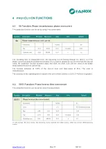
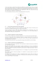
4.8.1. Thermal image measurement evolution graphic
On next graphic, thermal image measurement evolution can be observed depending on applied
current:
We suppose that thermal image protection has and adjusted tap of 1,1 times the nominal current and
an alarm level of 75%.
Zone 1: The machine is de-energized for a long time. Thermal image is 0%.
Zone 2: We supply the machine with the nominal current. Thermal image evolutions to get the
value of the thermal balance corresponding to one time the nominal current Th = (I/It)
2
= 82%.
The time that it takes in getting the thermal balance depends on the adjusted heating
constant.
Zone 3: Once reached the thermal image corresponding to the application of one time the
nominal current, we apply 1.2 times the nominal current. Thermal image would evolve to get
the thermal balance corresponding to 1.2 times the nominal current Th = (I/It)
2
= 119%. This
would occur if we had the permission of the thermal function disabled. If the permission is
disabled, 49 protection function performs when the thermal image reaches the value of 100%.
Once tripped, current is cut, and thermal image is getting cool based on the cooling constant.
Zone 4: Before getting totally cool, nominal current is applied again and thermal balance is
reached once passed the time determined by the heating thermal constant.
Thermal image protection alarm bit is active if the thermal image measurement is over the adjusted
alarm level.
Thermal image protection trip bit is active when the measurement of the thermal image is over 100%
and it is reset when the measurement of the thermal image is under the adjusted alarm level.
Th %
t
100%
1
2
3
4
75%
alarm
trip
Summary of Contents for SIA-F
Page 7: ...www fanox com Rev 17 7 119 2 DIMENSIONS AND CONNECTION DIAGRAMS 2 1 Frontal view...
Page 8: ...www fanox com Rev 17 8 119 2 2 Case dimensions The dimensions are in mm CUT OUT PATTERN...
Page 9: ...www fanox com Rev 17 9 119 2 3 Connection diagram 3 Phase CT and neutral CT Connection...
Page 10: ...www fanox com Rev 17 10 119 3 Phase CT and residual neutral Connection...
Page 34: ...www fanox com Rev 17 34 119...
Page 35: ...www fanox com Rev 17 35 119...
Page 36: ...www fanox com Rev 17 36 119...
Page 118: ...www fanox com Rev 17 118 119 NOTES...
Page 119: ...www fanox com Rev 17 119 119...


