


Rev.17
12/119
3.
DESCRIPTION
3.1.
Introduction
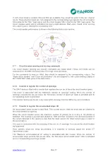
Worldwide, the energy sector is currently undergoing a profound change as a result of high levels of
energy demand; more distribution lines and advanced supervision systems are required. Given the
need for creating intelligent infrastructure, FANOX has developed the SIA family of products to carry
out this function.
The family of SIA relays is designed to protect the secondary transformation and distribution
substations of electricity grids. Protection features include protection against instantaneous and
inverse time overcurrent (for the phases and the neutral), and it also has external trip support
(temperature, pressure, etc.) depending on the characteristics of each model.
The protection functions can be enabled selectively by using both the front panel and the
communications links to the SICom program, allowing for precise coordination with another device.
3.2.
Device description
The SIA-F device is a protection relay designed for secondary distribution.
It is supplied with 24-220 Vac/48-230 Vac auxiliary voltage. As
for the rest of the SIA family, it can be supplied through its front
communications port connecting to PC directly using a USB
cable. This facilitates the start-up of the substations and the
management of events. The operation is guaranteed when the
SIA-F device is supplied from front USB port connector (mini
USB type A).
As well as the functions to protect against instantaneous phase
and neutral overcurrents and phase and neutral inverse time
overcurrents, it is possible to choose thermal image, circuit
braking monitoring and circuit breaker opening fault unit for
each model. It is also equipped with a trip blocking to protect
the switchgear in substations that combine switchgear and
fuses.
Depending on model it is included a breaker management
block, which monitors the switch condition, the number of
breaks and the accumulated amps. It generates an indication if
these are excessive, it determines whether an Opening fault
has occurred and allows the breaker close and open commands from the HMI and via the
communications port (either locally or remotely).
The SIA-F device has two inputs and two outputs that can be configured by the user (programmable
logic) apart from trip output and 3 LEDs.
In order to facilitate the analysis of events, it is fitted with 4 fault reports (16 events per fault report).
Fault report´s start can be configured by the user. Each register includes the events that have
occurred during the incident.
The SIA-F device is housed in a metal box with galvanic isolation on all its measurement or digital
inputs and outputs (with the exception of ports for communications). This allows the device to have the
best possible level of electromagnetic compatibility, both in terms of emission of, and immunity from,
radiated and conducted interferences. These levels are the same as those established for primary
substations.
Summary of Contents for SIA-F
Page 7: ...www fanox com Rev 17 7 119 2 DIMENSIONS AND CONNECTION DIAGRAMS 2 1 Frontal view...
Page 8: ...www fanox com Rev 17 8 119 2 2 Case dimensions The dimensions are in mm CUT OUT PATTERN...
Page 9: ...www fanox com Rev 17 9 119 2 3 Connection diagram 3 Phase CT and neutral CT Connection...
Page 10: ...www fanox com Rev 17 10 119 3 Phase CT and residual neutral Connection...
Page 34: ...www fanox com Rev 17 34 119...
Page 35: ...www fanox com Rev 17 35 119...
Page 36: ...www fanox com Rev 17 36 119...
Page 118: ...www fanox com Rev 17 118 119 NOTES...
Page 119: ...www fanox com Rev 17 119 119...


