background image


Model 520 HT UCA


D01157216 

Revision A, October 2015 

6  

1.1 

Document Conventions 

The following icons are used as necessary in this instruction manual. 


NOTE.

 Notes emphasize additional information that may be 

useful to the reader. 


CAUTION. 

Describes a situation or practice that requires operator 

awareness or action in order to avoid undesirable consequences.


MANDATORY ACTION

. Gives directions that, if not observed, 

could result in loss of data or in damage to equipment. 


WARNING! 

Describes an unsafe condition or practice that if not 

corrected, could result in personal injury or threat to health.


ELECTRICITY WARNING! 

Alerts the operator that there is risk of 

electric shock.


HOT SURFACE! 

Alerts the operator that there is a hot surface and 

that there is risk of getting burned if the surface is touched.


EXPLOSION RISK! 

Alerts the operator that there is risk of 

explosion.


Summary of Contents for 520 HT

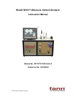
Page 1: ... 2015 Fann Instrument Company Model 520 HT Ultrasonic Cement Analyzer Instruction Manual Manual No D01157216 Revision A Instrument No 102546636 ...

Page 2: ...tus which may be covered by U S Patents Fann Instrument Company reserves the right to make improvements in design construction and appearance of our products without prior notice FANN and the FANN logo are registered trademarks of Fann Instrument Company in the United States and or other countries All other trademarks mentioned in the operating instructions are the exclusive property of the respec...

Page 3: ...est Setup Menu 15 5 3 New Temperature Profile 15 5 4 Instrument Setup Menu 17 5 5 Diagnostics 18 5 6 Running a Test 19 5 7 Stopping a Test 21 5 8 Using the USB Memory Module 21 5 9 Networking 22 5 10 Transit Time Calibration 22 6 Front Panel Controls 24 6 1 Hydraulic Pressure Controls 24 6 2 Pneumatic Controls 24 6 3 Electrical Controls and Displays 25 7 Operation 26 7 1 Setting Up Automatic Press...

Page 4: ...Model 520 HT UCA D01157216 Revision A October 2015 4 10 1 Warranty 35 10 2 Returns 35 ...

Page 5: ...e The Model 520 Ultrasonic Cement Analyzer UCA is used to provide a history of the strength development of a cement slurry as it cures under elevated temperature and pressure The UCA transmits an ultrasonic pulse through a cement slurry and measures the travel time of the pulse through the slurry The travel time of the pulse through the slurry gives an indication of the compressive strength of the...

Page 6: ...undesirable consequences MANDATORY ACTION Gives directions that if not observed could result in loss of data or in damage to equipment WARNING Describes an unsafe condition or practice that if not corrected could result in personal injury or threat to health ELECTRICITY WARNING Alerts the operator that there is risk of electric shock HOT SURFACE Alerts the operator that there is a hot surface and ...

Page 7: ...compressed air supply to the machine and carefully relieve air pressure from the machine 2 2 Safe Heating Before opening the pressure chamber use the cooling system to lower the temperature to at least 120 F 49 C The machine uses domestic water as coolant Shut off the domestic water supply before servicing NEVER operate the heater on an empty chamber The heater element will quickly overheat and fa...

Page 8: ...eved and viewed Text files txt may also be exported for interfacing with most word processors text editors spreadsheets and database programs Touch screen control panel controls of data acquisition and temperature Temperature profile is displayed graphically before test starts to reduce mistakes Available with integral pump and relief valve for soak pressure control It does not require separate pr...

Page 9: ...al Height 14 5 in 36 8 cm Width 26 in 66 cm Depth 15 3 in 38 9 cm Weight 110 lb 50 kg Environmental Operating Temperature 32 to 120 F 0 50 C Operating Humidity 0 95 non condensing Heater Heater Power 2 000 W Heater Type Cast heater with cooling coils Heater Control Solid state relay Utilities Water and Air Compressed Air 100 psig 6 8 bar Cooling Water Pressure 100 psig 6 8 bar maximum Utility Inle...

Page 10: ...llow the water filter manufacturer s recommended replacement interval Neglecting to install the water inlet filter will void the instrument warranty Water inlet supply water must be filtered at 5 micron or better and have a viscosity between 1 100 cst Pump performance is affected by many operating conditions Extreme temperatures pressures and high duty cycles will increase maintenance frequency Al...

Page 11: ...rical connections are made using the receptacle on the rear of the instrument A power cord is supplied with the instrument Please observe the following precautions when making the wiring connections Wiring should be completed by a qualified installer in accordance with local electrical codes The instrument should be securely connected to a separate earth ground The ground wire must be larger in di...

Page 12: ...t loss of test To connect the UPS select the power cord supplied with the UPS and connect one end to the UPS input and the other end to the UCA The cord will fit only one receptacle Locate the other power cord supplied with the instrument and connect one end to the output of the UPS and the other end to the other UPS receptacle on the rear of the UCA Press the ON button on the UPS A green light wi...

Page 13: ...e touch surface The purpose of the touch screen is to provide the user with a single interface to the instrument Temperature control instrument setup and current test data are accessed through the touch screen This eliminates the need to individually program separate temperature controllers or other off site software to begin running a test Additionally the touch screen allows the user to access c...

Page 14: ...ent test parameters and begins a new test If a temperature profile has been programmed a screen will prompt the user to turn on the heater Once a test has started the main testing screen will be displayed TEST SETUP This button takes the user to the Test Setup Screen Here the user may enter test parameters for the instrument Test name cement parameters UCA algorithm and Temperature Control are all...

Page 15: ...rom this menu the user can setup the parameters for the next test 5 3 New Temperature Profile On the temperature setup screen is a standard numeric keypad On the left side are three values that define a ramp Once a ramp is entered the user may advance to the NEXT STEP or press DONE to finish When finished a graph of the desired temperature ramp is displayed The user may ...

Page 16: ...e temperature must be the same After entering all of your ramps and soak you may press Done to complete the programming process If you press Done a graph will be displayed showing exactly what you have entered for your temperature profile as shown below From this screen the user may press OK if the graph is correct or Change to go back to the programming screens to correct any programming errors I...

Page 17: ...sts from the UCA to the USB memory module If the instrument reports a Disk Full message it will be necessary to do this before additional tests may be run After this step is completed the stored tests on the UCA are moved then deleted After this button is pressed a message box will appear indicating which files were copied from the UCA to the storage device CALIBRATE The Calibrate button gives the...

Page 18: ...ays a diagnostic screen where the user may pulse the transducer and display the waveform on the screen This tool allows the user to quickly verify transducer operation The peak of the transducer should be well above 200 with water in the vessel If the pulse amplitude is less than 200 with water in the cell the UCA will not function properly and an error message will be displayed ...

Page 19: ...parameters of the instrument from this menu Under the Pressure column the user can turn the water supply to the pressure vessel on or off and can turn the pump on when the cylinder is filled Under the Temperature column the user can select between AUTO and MANUAL temperature control When in MANUAL mode the user can adjust the temperature set point as well as turn cooling on off ...

Page 20: ...n Please note that a printer must be connected to the instrument before trying to print Pressing the PRINT button displays the full TEST VIEWER screen where the user may select specific printing options such as header footer information before printing to any installed printer A complete table of numerical data can also be viewed here by selecting the DATA tab located on the left side of the scree...

Page 21: ...er data will be logged and no further temperature control will be provided You may view the last test or any test stored on the UCA by pressing the VIEW TEST button and selecting the appropriate file name 5 8 Using the USB Memory Module The UCA operates under a version of the Windows operating system This allows the use of certain Universal Serial Bus USB peripherals such as USB flash memory modul...

Page 22: ...er on the network It is also possible to view a UCA test in progress or an old test from another computer networked to the UCA using the UCA Remote Viewer software This will allow personnel to view a test in progress from home or on location provided they have access to the network to which the UCA is connected Since the UCA operates under Microsoft Windows 98 or later the instrument can be easily...

Page 23: ...eneral the peak amplitude should be 600 or greater with water If an acceptable waveform is not displayed check the transducers and cables and recalibrate Transit time calibration is different from older UCAs The steel calibration bar is no longer required The unit is now calibrated with water It is imperative that there be no air in the water during calibration or while a test is in progress Incor...

Page 24: ...r valve will open and release pressure until the hydraulic and spring forces balance again The regulator will then close preventing any additional pressure release until the hydraulic force again exceeds the spring force Turn the PRESSURE REGULATOR knob clockwise to increase pressure and counterclockwise to reduce pressure The pressure regulator is only usable at pressures up to 10 000 psig 680 ba...

Page 25: ... the hydraulic pressures increases and vice versa Air pressure to the pump may be decreased by turning the AIR TO PUMP regulator knob counterclockwise or increased by turning the knob clockwise If the regulator is set to a value and the pump switch is turned to the ON position the pump will increase pressure until the pneumatic force of the air air pressure multiplied by pneumatic piston area equa...

Page 26: ...he upper tab marked DRY Be careful not to get cement into the threads If cement sets up in the threads it may make plug removal and installation difficult or impossible 4 Gently pour a small amount of water into cylinder on top of the cement just enough to reach the water fill line on the Slurry Level Gauge Try not to mix the water and cement 5 Screw the top plug in place Do not tighten with a wre...

Page 27: ... be placed near the thermocouple vent hole to collect the spilled water and prevent it from running down inside the instrument or into the sensor cavity 7 1 Setting Up Automatic Pressure Control This section describes the steps used to control pressure in the Model 520 UCA Use of the internal pump and pressure regulator will also be discussed Follow the steps below to configure the pump and pressu...

Page 28: ...uced If the heating rate is reduced as during the transition from a temperature ramp to a temperature soak the pressure in the test cylinder may decrease If the pressure falls below the control pressure lower limit the pump will actuate and bring the pressure back within the established limits The pump and pressure regulator will have hysteresis or a deadband in their operation For example if the ...

Page 29: ...nd confirm Next press the Windows Start button on bottom left of screen and Shut down computer properly 5 Turn POWER switch to its OFF position 6 Close the PRESSURE RELEASE valve clockwise Failure to do so will result in water leakage if cooling water is circulating when the U tube or thermocouple are loosened 7 Remove the U shaped high pressure tubing connecting the test cylinder to the bulkhead ...

Page 30: ...ly In some cases it may make removal of the bottom plug more difficult Its use is strictly optional and may be omitted if desired 2 Remove the cylinder from the vice and replace in the vice top side down 3 Unscrew and remove the bottom plug from the test cylinder 4 Turn the cylinder over and tap the cement sample out of the test cell with a hammer The cylinder is tapered outward from top to bottom...

Page 31: ...present to get the density above 17 5 lb gal We recommend performing a mechanical compressive strength test to see the actual compressive strength If the results are within 200 psi then it is considered the correct algorithm If not try a different algorithm You can easily change algorithms using the Test Viewer to see which algorithm best fits your data The algorithms developed by Halliburton in t...

Page 32: ...ate problem and correct Test cylinder has trapped air Open thermocouple connector slightly and release trapped air WATER SUPPLY valve is not open or water is not being supplied to the instrument Open WATER SUPPLY valve and check flow of water to the instrument PRESSURE REGULATOR is not holding pressure Turn PRESSURE REGULATOR knob clockwise Overhaul replace regulator Faulty pump check valve Clean ...

Page 33: ...ump is not functioning If no solenoid click is heard when the PUMP switch is turned to the ON position a faulty solenoid valve is likely Waveform amplitude is too low Not enough ultrasonic couplant on transducers Pressure is below 1000 psi Dirt or debris on transducer faces Clean transducers and apply new couplant Pea size amount is sufficient Increase pressure above 1000 psi Clean transducers and...

Page 34: ...ure to inspect the o rings for damage and replace if damaged or severely distorted It is recommended that the thermocouple and water line connections on the top plug be cleaned periodically to prevent buildup of cement in the bore and threads Problems related to corrosion of the lower transducer connection can be minimized by not allowing water to run down the side of the cylinder and into the bot...

Page 35: ...talogs literature or brochures of materials used in the manufacture of its products Fann reserves the right to substitute other materials without notice Fann does not warrant in any way equipment products and material not manufactured by Fann and such will be sold only with the warranties if any that are given by the manufacturer thereof Fann will only pass through to Customer the warranty granted...

Reviews: