Gnd
15
g
When an
A
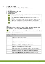
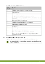
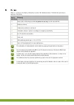
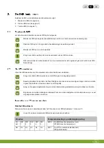
is shown in the display, followed by a number, this indicates an alarm. The table below provides an
overview of the alarms.
Alarm
indication
Meaning
A0
Backup alarm: No settings available,
adjustment necessary
! (via I/O network A100)
A1
Defective memory.
A2
Intake valve position is not achieved.
A3
Interruption of power, system is operating on emergency power facility.
A4
No I/O network communication.
A7
Alarm test
A8
IMS outside adjusted range (< -1% or > 101%)
A9
Open or Close adjustment is not successfully done.
The notification of a retracted alarm can be deleted by pressing the pushbutton on the printout.
A control computer connected to the IMS via an I/O network can take over the alarm notification (as
long as this functionality is supported).
An alarm test (
A7
) can be executed by pressing the pushbutton until the indication
A
is shown in the
display. For this, the rotating switch should be operated manually.
The calibration value for a maximum position may expire in the event of unpowered overload.
An interruption of power supply due to overload may cause the calibration value to expire in the event of
a maximum stroke in the fully open position.
Summary of Contents for IMS
Page 1: ...G N D Gnd...
Page 20: ...Gnd 17 g...
Page 21: ...Gnd 18 g...
Page 29: ...gNd 5 n...
Page 41: ...gNd 17 n...
Page 42: ...gNd 18 n...
Page 62: ...gnD 17 d...
Page 63: ...gnD 18 d...


