Gnd
11
g
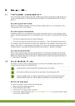
Initial position adjustments must be performed in the following order: first close, followed by open.
Afterwards these positions can be fine-tuned.
Changing between 10-0V and 0-10V, or vice versa, must be preceded by restoring factory settings.
For 10-0V or 0-10V control, you should ensure that the control computer's analogue output sends out
1%. Recommendable is 9.5V if a 10-0V voltage control is used. (For an I/O network control system this
is not important.)
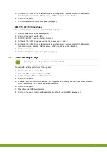
1. Set the manual switch to the
CLOSE
position (
) and allow the air intake valve to close.
2. Set the manual switch to an OFF (
O
) position.
3. If a potentiometer is used, turn it completely to the left. (Not necessary if a CPS is used. Go to the next step.)
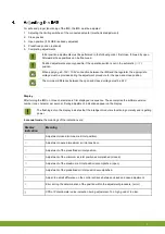
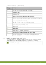
4. Press the pushbutton until the number 1 appears in the display and then release the pushbutton. The IMS is
now in the 1% adjustment mode. After releasing the pushbutton, a dash will appear in the display.
5. If a potentiometer is used, adjust it with a screwdriver such that the dash is in the middle position of the
display. (Not necessary if a CPS is used. Go to the next step.) If the dash is not in the middle, the stroke is to
short. Close the motor a bit more or change the open adjustment, but make sure the inlet close position is
correct.
6. Press the pushbutton to confirm the setting. The letter
C
now appears in the display. This means that the
adjustment was successful.
Is there something other than
C
in the display? Then the adjustment was not successful. If no
improvement occurs, restore to factory settings.
Summary of Contents for IMS
Page 1: ...G N D Gnd...
Page 20: ...Gnd 17 g...
Page 21: ...Gnd 18 g...
Page 29: ...gNd 5 n...
Page 41: ...gNd 17 n...
Page 42: ...gNd 18 n...
Page 62: ...gnD 17 d...
Page 63: ...gnD 18 d...


