background image

SAFETY PRECAUTIONS 

Rev 3.0


Fanco Infinity DC. All Rights Reserved.


6.


The hanger bracket must be firmly screwed to a load bearing building structure e.g. a concrete 

ceiling, steel structure, or a timber frame. If additional timber frames are to be added, those must 

be securely nailed or screwed between the beams. 

7.


Attach fan blades after the fan motor housing is installed and properly secured. Keep the fan 
motor and blades in the original package until it is ready to be installed. 

8.


Check  and  confirm,  after  the  fan  is  completely  installed,  that  all  connections  are  proper  and 

secure to prevent the fan from falling or causing property damages or personal injury. 

9.


Take care not to bend or damage the motor Drive Shaft or Fan Blades when handling or installing 

them. If such defect is noticed, please contact the Customer Service before installation of the 
ceiling fan. 

10.


Both the fan with light kit and the hanging bracket must be earthed. 

11.


Do not remove the fan from the ceiling after installation. 

12.


Make sure electricity is turned off at the main power box before commencing work. Turn off the 
power by removing fuse or turning off circuit breaker before installing the fan. 


ELECTRICIANS AND INSTALLERS NOTICES 

1.


The 

AUSTRALIAN CONSUMER LAW ACT 2010

 mandates consumer protection against defects 

or  poor  workmanship  in  provision  of  services  (such  as  installing  a  ceiling  fan).  To  protect 
yourself and the consumer, these instructions must be followed. Failure to do so may result in 

the consumer making claim against you for consequential loss or damage. 


2.


If there are any problems with the products at the time of installation, the installer must contact 
the Customer Care Hotline (located on the Warranty Card) 

BEFORE

 leaving the job site. 


3.


Do not remove the fan from the ceiling once installed, unless instructed to do so.  


CLEARANCES AND ANGLED CEILING 


*Fan shown are for illustration 

purposes only. Actual product may vary.


(Minimum

2.1m  

(Minimum) 

       1.5m 

19

˚ (max)


Floor level 

(Recommended) 

 1.5m 

(Recommended) 

          1.0m 

Raked Ceiling 

Summary of Contents for CFFCINI2LWH

Page 1: ...strated and that which is contained within this package INSTALLATION AND OPERATION INSTRUCTION BOOK REV 3 0 INFINITY LED DC SERIES Models CFFCINI2LWH FC818123WW CEILING FANS WITH LIGHT CAUTION DO NOT...

Page 2: ...PECIFICATIONS 1 SPARE PARTS ACCESSORIES 2 SAFETY PRECAUTIONS 3 UNPACKING YOUR CEILING FAN 5 FAN INSTALLATION INSTRUCTIONS 6 REMOTE PAIRING INSTRUCTIONS 9 WIRING DIAGRAM 11 REMOTE CONTROLLER INSTRUCTIO...

Page 3: ...on to an installation procedure operating procedure maintenance procedure or the like that if not correctly performed or adhered to could result in damage to this appliance personal injury or death Do...

Page 4: ...ed SPARE PARTS LIST MODEL BLADES REMOTE CONTROL LAMP COVER SCREWS PACK HANGER BRACKET CFFCINI2LWH FL818123WH FRM105 FG488123 FR488123WH FHB48311553 OPTIONAL ACCESSORIES SOLD SEPARATELY MODEL 600 mm EX...

Page 5: ...ly 6 Do not use outdoors where it could be exposed to water or moisture 7 If unusual oscillating movement is observed immediately stop using the ceiling fan and contact licensed electrician or Fanco C...

Page 6: ...hanging bracket must be earthed 11 Do not remove the fan from the ceiling after installation 12 Make sure electricity is turned off at the main power box before commencing work Turn off the power by r...

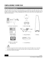
Page 7: ...ow away the carton or other packaging material as it may be needed if warranty replacement or repair is ever necessary 1 x Remote Controller Set 1 x Motor Assembly Balancing Kit Screws Package 1 x Han...

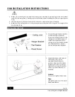
Page 8: ...to support the weight of the fan of about 35 kg INSTALLING THE FAN 1 Fan and hanger bracket must be earthed during installation Secure the hanger bracket to the ceiling joist or suitable piece of tim...

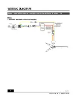
Page 9: ...l engages the ridge on the hanger bracket This will allow hands free wiring Connect the wires in accordance to the wiring diagram provided 4 Place the remote receiver inside the fan canopy and connect...

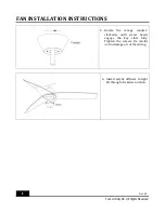
Page 10: ...Infinity DC All Rights Reserved 5 Rotate the canopy counter clockwise until screw heads engage the key slots fully Tighten the screws Be careful not to damage or cut the wiring 6 Install acrylic diff...

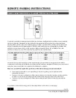
Page 11: ...sented by 1 OFF setting represented by 0 0000 0100 1000 1100 0001 0101 1001 1101 0010 0110 1010 1110 0011 0111 1011 1111 A remote receiver must undergo an ID code learning process before it recognises...

Page 12: ...all switch in the fixed wirings for each fan 2 Turn ON the power to all receivers for all fans 3 Press the transmitter s SET 4 buttons and hold both buttons for over 5 seconds 4 The receiver will beep...

Page 13: ...WIRING DIAGRAM 11 Rev 3 0 Fanco Infinity DC All Rights Reserved WIRING DIAGRAM FOR FAN CONTROLLED WITH REMOTE CONTROLLER...

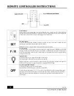
Page 14: ...uld ideally be set to move blades in anticlockwise direction for downwards airflow during summer seasons and to move blades in clockwise direction for upwards airflow during cooler seasons Light ON OF...

Page 15: ...ighten III Re tighten all screws in the hanging bracket and covering plate 3 MECHANICAL NOISE I Let the fan run for about 8 hours for settling in period 4 FAN TURNS BUT DOES NOT MOVE MUCH AIR I The fa...

Page 16: ...winter reverse the switch fan should spin in clock wise direction so that an upward airflow will push warm air off the ceiling and circulate it downwards into the living areas In winter months use the...

Reviews: