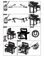
Whilst grill is lit, test all integral gas carrying joints and components for gas soundness. Use a suitable
leak detection fluid.
TURN OFF gas control tap. REMOVE pressure gauge and replace test point sealing screw.
ENSURE THAT A GAS TIGHT JOINT IS MADE.
Re-assemble all panels and components removed during installation and commissioning. The drip
tray, wire grid and brander can then be placed in position.
2.6
Instruction to User
Hand over User manual. Ensure user understands the procedures for lighting, cleaning and correct
use of appliance. Point out the location of the isolating cock which may require to be shut down in
event of an emergency.
SECTION 3
– SERVICING AND CONVERSION
Important -
Before carrying out any inspection, servicing or exchange of components, turn OFF the gas at the
isolating cock and take steps to ensure that it is not inadvertently turned on. Always remove the brander and
grid shelf.
After any maintenance task, check the appliance to ensure that it performs correctly and carry out any
necessary adjustments as detailed in Section 1.
After carrying out any servicing or exchange of gas carrying components
–
ALWAYS CHECK FOR GAS SOUNDNESS
3.1
Gas Conversion Check list
To convert from NATURAL to PROPANE gas
–
Change main, cross lighting and pilot injectors,
Remove governor and check supply pressure accordingly, (section 1.9).
Adjust aeration.
Adjust Low flame / Turndown setting, (section 2.5.3).
Change data plate.
To Convert from PROPANE to NATURAL gas
Change main, cross lighting and pilot injectors.
Connect governor and adjust inlet pressure accordingly, (section 1.9).
Adjust aeration.
Adjust Low flame / Turndown setting, (section 2.5.3).
Change data plate.
3.2
Removal of Plaques and Burners;
Warning: To avoid burns, ensure grill is at room temperature before removing components.
3.2.1 Plaques Only;
a) Remove drip tray, grid shelf and brander.
b) Plaques may be replaced by reaching inside compartment top and placing your fingers on plaque
face. Push plaque up carefully to dislodge it from seating between bars and support angle.
c) Carefully replace plaque so that it is properly seated on bar and support angle. The plaque should
be positioned hard against the burner.
3.2.2 Burners
a) Remove top fixings from LH and RH outer side panels.
b) Remove top panel by lifting up from the front and pulling forwards to release tabs from back panel.
c) Remove bottom and rear fixings from LH outer side panel
(viewed from rear)
and lift clear.
d) Remove bottom and side fixings from outer back and lift clear.
e) Remove inner top panel above burners by loosening two fixings at LH side and removing six
fixings at rear, and lift top panel clear.
f) Reach inside top of compartment and remove ceramic plaques and support bars.


