


8
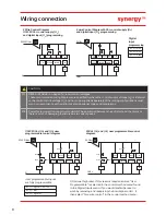
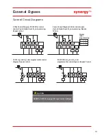
3 wire Control Diagram 24Vdc control supply (U
S
)
and digital input (U
C
) programming.
Digital
input
programming
D1 - 1I
= Start
D1 - 2I
= Stop
D2 - 1I
= Reset
3 Wire Control Diagram
110/230Vac control supply (U
S
)
and digital input (U
C
) programming.
L
D1-2I
D1-1I
D2-1I
33
N
D2COM
D1COM
34
K1
24
Vdc
D1-2I
D1-1I
D2-1I
33
0Vdc
D2COM
D1COM
34
K1
!
!
L
D1-2I
D1-1I
D2-1I
33
N
D2COM
D1COM
34
K1
24
Vdc
D1-2I
D1-1I
D2-1I
33
0Vdc
D2COM
D1COM
34
K1
!
!
110/230Vac
N
User programmable Inputs
are fully programmable
D1 - 1I
= High Start / Low Stop
D1 - 2I
= None
D2 - 1I
= High Reset
1) Optional high reset. If this reset is required ensure “User
Programmable” is selected in the control method menu found
in the Digital Inputs menu. If you would prefer the reset to
work by removing and reapplying the Start Signal on D1 - 1
I
then select “Two wire control” in the control method menu.
24Vdc
0Vdc
24Vdc
0Vdc
D1-1I
Stop
Start
D2-1I
33
D2COM
D1COM
34
K1
K2
K2.1
K2.2
1)
!
L
D1-1I
Stop
Start
D2-1I
33
N
D2COM
D1COM
34
K1
K2
K2.1
K2.2
1)
!
110/230Vac
24Vdc
0Vdc
N
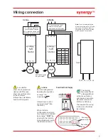
Wiring connection
CAUTION
#1
REFER to TABLE 1 on page 6 for input control voltages.
These recommended wiring diagrams are specifically where the control supply voltage (U
S
) is identical
to the control circuit voltage (U
C
) and not to be supplied separately. Other wiring configurations must
also be in accordance with existing local and national codes and regulations.
#2
Power factor correction capacitors must NOT be positioned between the soft start and the motor or
there is a risk of damaging thyristors due to current peaks.
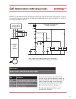
110/230Vac (U
S
) and (U
C
) user
programmable control diagram
24Vdc (U
S
) and (U
C
) user programmable control
diagram.
Summary of Contents for Synergy SGY-401
Page 1: ...synergy Quick Start Guide SGY 401 to SGY 505...
Page 18: ...18 Notes...
Page 19: ...19 Notes...


