Fairford Synergy SGY-401 Quick Start Manual Download Page 17

17


Please note for higher temperatures (>60

o

C) and altitudes (>2000m) contact your supplier.

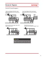
Short circuit protection

#1 Suitable for use in a circuit delivering not more than __Iq__ rms Symmetrical Amperes, 480 

Volts maximum, when protected by Class J time delay fuses with a maximum rating of __Z1__ or 
by a circuit breaker with a maximum rating of __Z2___ as in table below.

#2 Correctly selected semiconductor fuses can provide additional protection against damage to 

the synergy

 unit (this is sometimes referred to as type 2 co-ordination). These semiconductor 

fuses are recommended to provide this increased protection

-20°C (-4°F) to 40°C (104°F). Above 40°C de-rate linearly by 4% of synergy

 Ie per °C to a 

maximum of 60°C (140°F).

Altitude above sea level 1000m (3281ft). Above 1000m de rate by 1% of 


synergy

 Ie per 100m (328ft) to a maximum altitude of 2000m (6562ft).
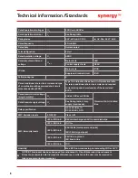
 

Standards

Type designation (e.g. SGY-201)

SGY

401

SGY

403

SGY

501

SGY 

503

SGY 

505

Rated operational 
current

I

e

A

610

722

850

960

1080

Rated conditional 
short circuit current

I

q

kA

30

30

42

42

42

Semiconductor fuse 
(class aR) #2

Type

A

Bussmann 170M5466

Siba 2067132.1000A

Bussmann 170M6467

Siba 2068132.1400A

Fuse rating

A

1000

1400

Terminal 

Models

Wire Size

Torque 

mm

2

AWG

Nm

lb-in

Main Terminals
Copper busbar

2 x M10 bolt

SGY-401 to SGY-403

50 x 10

1.5in x 0.5in

14

123

M12 bolt

SGY-501 to SGY-503

60 x 10

2.0in x 0.5in

SGY-505

80 x 10

2.5in x 0.5in

Control terminals

All models

0.2-1.5

24-16

0.5

4.5

Protective Earth 

1)


Cu Only

M8 stud

SGY-401 to SGY-403

> 70

> 1/0

12

105

M10 stud

SGY-501 to SGY-503

> 70

> 2/0

SGY-505

> 95

> 3/0

1) Protective Earth wire size based on bonding conductor requirements of UL508 and UL508A and CSA C22. No.14

Wire sizes and torques

Summary of Contents for Synergy SGY-401

Page 1: ...synergy Quick Start Guide SGY 401 to SGY 505...

Page 2: ...machines and chillers can typically see savings of around 8 40 of total energy consumption when lightly loaded With size and cabinet capacity an ever increasing focus Fairford developed the world s s...

Page 3: ...ent will responsibility or liability be accepted for direct indirect or consequential damages resulting from the use or application of this equipment Short Circuit Fairford soft starts are not short c...

Page 4: ...4 SGY 401 to SGY 403 Weight 72 0 kg 158 7lbs Fitting Environment installation Weight 65 00 kg 143 3lbs Dimensions SGY 501 to SGY 505...

Page 5: ...ion occurs when energy saving Heat dissipated can be approximated with the formula Watts synergy synergy current rating x 3 With external bypass installed the formula becomes Watts synergy 1 2 x syner...

Page 6: ...W Residual ripple 100mV Spikes switching Peaks 240mV Turn On Off response No overshoot of V out Overvoltage voltage protection output voltage must be clamped to 30Vdc SGY 401 to SGY 505 Control Power...

Page 7: ...equation synergy Ie ie motor Allows lower current rating synergy than the motor When In Delta configuration is used a line contactor controlled by synergy MUST be used with the In Delta Firing Mode s...

Page 8: ...work by removing and reapplying the Start Signal on D1 1I then select Two wire control in the control method menu 24Vdc 0Vdc 24Vdc 0Vdc D1 1I Stop Start D2 1I 33 D2COM D1COM 34 K1 K2 K2 1 K2 2 1 L D1...

Page 9: ...lied to the starter motor before the motor field has had some chance to die away The thermal capabilities of synergy should be considered Note forward and reverse buttons must remain pressed for longe...

Page 10: ...ol Supply K1 K3 T1 K2 TR B1 T2 B2 K0 Notes Soft Starter must have stop time set to 0 T1 Time between K1 or K3 closing and the starter being energised 0 5 sec minimum T2 Time between B1 closing and K3...

Page 11: ...ansformer CT cables pre installed colour coding corresponds to the phase wiring identification Attatch the CT cables to the transformers adhering to the numbering scheme If the motor overload function...

Page 12: ...tarting ramp a bypass contactor is closed effectively removing the thyristors from circuit which in turn eliminates heating losses The contactor is controlled by a programmable relay set to End of Sta...

Page 13: ...1I D2 1I 33 N D2COM D1COM 34 K1 24 Vdc D1 2I D1 1I D2 1I 33 0Vdc D2COM D1COM 34 K1 44 K3 44 K3 L D1 1I Stop Start D2 1I 33 N D2COM D1COM 34 K1 K2 K2 1 K2 2 1 44 K3 L D1 1I Stop Start D2 1I 33 N D2COM...

Page 14: ...14 1 3 5 7 6 8 2 4 Please note Only appears if application with a trip class higher than 10 is selected Setup Wizard OL I P 0 0A 0kW Programming...

Page 15: ...72 1 primary series corresponding to IEC current rating 2 Rated operational powers in HP ased on Table 430 250 of the National Electrical Code 2005 corresponding to FLA current rating 3 The IEC Ie rat...

Page 16: ...nt rating and characteristics of the associated SCPD Rated control circuit voltage programmable Uc 24Vdc 110Vac or 230Vac Protect with 4A UL Listed fuse Rated control supply voltage Us See Rating tabl...

Page 17: ...3281ft Above 1000m de rate by 1 of synergy Ie per 100m 328ft to a maximum altitude of 2000m 6562ft Standards Type designation e g SGY 201 SGY 401 SGY 403 SGY 501 SGY 503 SGY 505 Rated operational curr...

Page 18: ...18 Notes...

Page 19: ...19 Notes...

Page 20: ...ta saaneet henkil t saavat suorittaa seuraavat ty t Nebezpe razu elektrick m proudem N e uveden pr ce sm j prov d t pouze osoby s elektrotechnick m vzd l n m Eluohtlik Elektril gioht J rgnevalt kirjel...

Reviews: