


7
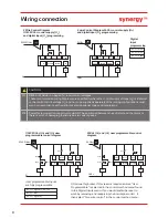
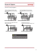
In Delta
In Line
Induction
Motor
U1
U2
V2
W2
V1
W1
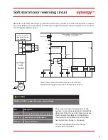
Induction
Motor
Terml
Fwd
Rev
2/T1
U1
U1
4/T2
V1
W1
6/T3
W1
V1
1/L1
W2
V2
3/L2
U2
U2
5/L3
V2
W2
K1 - Main contactor or
circuit breaker isolation
and protection switch gear
(provided by the customer)
K1 - Main contactor and
protection switch gear
(provided by the customer)
Note: Circuit breaker isolation
alone is not allowed for In Delta
operation. K1 (Main contactor)
controlled by the Running relay
MUST be used for isolation.
Soft start must
be grounded
In Delta
For this configuration
applying the equation.
synergy™ Ie =
ie (motor)/
Allows lower current
rating synergy
™
than
the motor.
When In Delta
configuration is used a
line contactor controlled
by synergy
™
MUST
be
used with the In Delta
Firing Mode selected in
the advanced menu.
For suitable
short circuit protection
devices (SCPD’s) see
short Circuit Protection
in the Technical
Information/ standards
section of this guide.
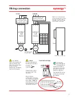
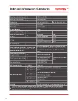
Wiring connection
L1 L2 L3
L1 L2 L3
T1 T2 T3
T1 T2 T3
synergy
™
Soft
Starter
synergy
™
Soft
Starter
T1, T2, T3 L1, L2, L3
Front
Fan Electrical Suply
The cooling
fans are of fixed
voltage (defined
at the time of order),
and require a seperate
electrical connection
(110Vac or 230Vac).
The required fan rating
is shown on the label
(see below)
Fan supply
connections
Fan voltage
rating
3
Summary of Contents for Synergy SGY-401
Page 1: ...synergy Quick Start Guide SGY 401 to SGY 505...
Page 18: ...18 Notes...
Page 19: ...19 Notes...


