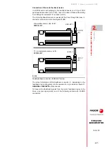
3-phase servomotors. FXM
2.
3-PHASE SERVOMOTORS. FXM
Co
nne
ctio
ns
98
· 48 ·
Ref.2105
FXM|FKM
SERVOMOTOR
FAGOR supplies the EEC-SP-
feedback cable upon request.
If you use to manufacture you own cable, read the following instructions
carefully to understand the diagrams correctly. Observe that there are two
cables indicated as type I and type II. Any of the cables shown is valid as
feedback cable for a sinusoidal encoder. Only the wire colors are different,
the connections are the same.
Here are the diagrams of the two cables (respecting the colors of the
wires) supplied by FAGOR upon request.
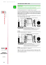
Sinusoidal encoder. EEC-SP-
cable
INFORMATION.
Using the EEC-SP-
cable as motor feedback cable ensures compliance
with Directive 2014/30/EU on Electromagnetic Compatibility.
i
F- 2/10
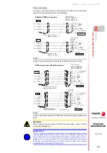
Encoder connection EEC-SP-
. Cable type I.
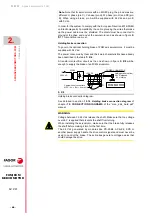
F- 2/11
Encoder connection EEC-SP-
. Cable type II.
Note.
This cable may be connected to AXD, ACD, MMC and CMC
drives as well as to ACSD-
H and MCS-
H drives. For the latter, see
their corresponding manual.
(HD,
Sub-D,
M26)
Blue
Black
Green
Brown
Grey
Purple
White
Red
Ready made cable
EEC-SP-03/05/06/07/08/09/10/11/12/15/20/25/30/35/40/45/50/60
Length in meters; connectors included
10
2
6
5
1
8
3
4
12
REFCOS
SIN
REFSIN
+485
- 485
GND
TEMP
TEMP
+8 V
COS
7
20
19
11
2
10
1
21
22
26
25
23
Yellow
9
Cable 3x2x0.14 +4x0.14+2x0.5
Signal Pin
Pin
CHASSIS
EOC-12
Front view
Front view
to FXM motor
connector ·2·
(0.5 mm
2
)
(0.5 mm
2
)
Shielded by pairs of cable. Overall shield.
The shield of twister pairs must be connected to each other and only at the drive
end joined to the common pin of the chassis (pin 26).
The overall screen must be connected to the connector housing at the drive end
and to the metallic housing and to pin 9 of the connector at the motor end.
The housing of the 26-pin connector must be conductive (metallic).
Black
9
1
26
19
to AXD/ACD drive
connector ·X4·
· with A winding ·
type I
(HD,
Sub-D,
M26)
Orange
Black
Green
Brown
Grey
Red
Blue
Brown-Red
Ready made cable
EEC-SP-03/05/06/07/08/09/10/11/12/15/20/25/30/35/40/45/50/60
Length in meters; connectors included
10
2
6
5
1
8
3
4
12
REFCOS
SIN
REFSIN
+485
- 485
GND
+8 V
COS
7
20
19
11
2
10
1
21
22
26
25
23
Yellow
9
Cable 3x2x0.14 +4x0.14+2x0.5
Signal Pin
Pin
CHASSIS
Front view
to AXD/ACD drive
connector ·X4·
(0.5 mm
2
)
(0.5 mm
2
)
Brown-Blue
9
1
26
19
TEMP
TEMP
EOC-12
Front view
to FXM motor
connector ·2·
· with A winding ·
Shielded by pairs of cable. Overall shield.
The shield of twister pairs must be connected to each other and only at the drive
end joined to the common pin of the chassis (pin 26).
The overall screen must be connected to the connector housing at the drive end
and to the metallic housing and to pin 9 of the connector at the motor end.
The housing of the 26-pin connector must be conductive (metallic).
type II

