background image

‡ ‡ ‡

 Quick reference

17

(S

OFT

 03.1

X

)

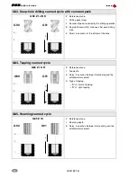
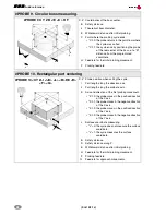
G86. Boring canned cycle

G86 Z I K R

Z

Reference plane.

I

Boring depth.

K

Delay, in seconds, between the boring and the 
withdrawal movement.

R

Type of withdrawal:

• "R"=0: in rapid (G00).
• "R"=1: At work feedrate (G01).

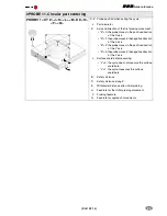
G87. Rectangular pocket canned cycle.

G87 Z I D A J K M Q B C L H V

Z

Reference plane.

I

Pocket depth.

D

Distance between the reference plane and the part 
surface. 

A

Angle, in degrees, between the pocket and the 
abscissa axis.

J

Half length of the pocket.

K

Half width of the pocket.

M

Type of corner:

• "M"=0: square
• "M"=1: rounded
• "M"=2: chamfer.

Q

Rounding radius or chamfer size.

B

Depth of pass.

C

Milling pass or width.

L

Finishing pass.

H

Feedrate for the finishing pass.

V

Tool penetrating feedrate.

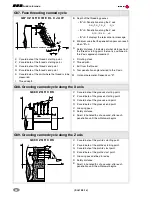
G88. Circular pocket canned cycle

G88 Z I D J B C L H V

Z

Reference plane.

I

Pocket depth.

D

Distance between the reference plane and the part 
surface.

J

Pocket radius.

B

Depth of pass.

C

Milling pass or width.

L

Finishing pass.

H

Feedrate for the finishing pass.

V

Tool penetrating feedrate.

G90

Z

I

Zi

Z

I

G91

Z i

Z   (G9 0)

I  (G 90)

I  (G 91)

Z  (G 91)

J

D

B

(X , Y )

K

A

Z i

Z (G 90 )

I  (G9 0 )

I  (G9 1 )

Z (G 91 )

( X,Y )

J

D

B

Summary of Contents for CNC 8070

Page 1: ...Quick reference SOFT 03 1X REF 0706 CNC 8070...

Page 2: ...8 Editing simulation mode 10 List of G functions 11 List of M functions 13 Technological functions 14 Milling canned cycles 15 Turning canned cycles 18 Probing canned cycles milling 25 Probing canned...

Page 3: ...he manufacturer B Icon showing the status of the program of the active channel C Program selected in the active channel for execution D Number of the block in execution The bottom icon indicates that...

Page 4: ...e CTRL F12 Configurable mode It may be configured using machine parameter USERKEY To show the modes window CTRL A Using the screens Previous menu CTRL F1 Switch window CTRL F2 Key that may be customiz...

Page 5: ...hide the CNC message list CTRL K Show hide the calculator ALT S Show hide the channel synchronization window Program editor CTRL TAB Toggle between the editor and the error window CTRL C Copy the sele...

Page 6: ...keyboard Press the home search key Press START to carry out a home search Press ESC to cancel the operation Automatic Press the home search key Press START to carry out a home search Press ESC to canc...

Page 7: ...he axis to be jogged If several axes are selected simultaneously they all move at the same time The CNC moves each axis as the handwheel is turned depending on the setting of the selector switch and o...

Page 8: ...d for calibration Select the tool and the offset The CNC places the tool into the spindle and shows the dimensions defined in the tool table for that offset Use the MDI mode to start the spindle Appro...

Page 9: ...work mode Edit and execute individual blocks Save the set of blocks executed as an independent program Standard MDI window It is possible to edit and execute new blocks or recover blocks saved in the...

Page 10: ...n mode Tool inspection This option is only available when the running program has been interrupted Press the relevant key to start the tool inspection Reposition the axes and the spindle To end toolin...

Page 11: ...bottom window Press ENTER to open the program Press ESC to cancel the selection and close the list of programs Number of times It sets as stop condition that the block selected as the stop block has b...

Page 12: ...the editing window and its name appears at the bottom center of the screen The program simulation procedure is the following Choose the type of graphic representation its dimensions and the point of...

Page 13: ...he channel G13 Mirror image on the third axis of the channel G14 Mirror image in the programmed directions G17 Main plane X Y and longitudinal axis Z G18 Main plane Z X and longitudinal axis Y G19 Mai...

Page 14: ...f acceleration to be applied to all the axes G132 Percentage of jerk to be applied per axis G133 Percentage of jerk to be applied to all the axes G134 Percentage of Feed Forward to be applied G135 Per...

Page 15: ...63 Arc radius programming G264 Cancellation of arc center correction G265 Activation of arc center correction G266 Feedrate override at 100 LIST OF M FUNCTIONS Function Meaning M00 Program stop M01 Co...

Page 16: ...of the channel may be programmed in the same block The programmed speed stays active until another value is programmed The programming units will be RPM unless selected otherwise If G96 is active the...

Page 17: ...K Delay in seconds between the drilling and the withdrawal movement G82 Drilling canned cycle with variable peck G82 Z I D B H C J K R L Z Reference plane I Drilling depth D Distance between the refer...

Page 18: ...lling step K Dwell in seconds at the bottom of the hole G84 Tapping canned cycle G84 Z I K R Z Reference plane I Tap depth K Delay in seconds between the tapping and the withdrawal movement R Type of...

Page 19: ...xis J Half length of the pocket K Half width of the pocket M Type of corner M 0 square M 1 rounded M 2 chamfer Q Rounding radius or chamfer size B Depth of pass C Milling pass or width L Finishing pas...

Page 20: ...Label number of the first block describing the geometry of the profile E Label number of the last block describing the geometry of the profile P Number of the subroutine where that defines the profil...

Page 21: ...with straight sections G81 X Z Q R C D L M F H X X coordinate of the profile s starting point Z Z coordinate of the profile s starting point Q X coordinate of the profile s last point R Z coordinate o...

Page 22: ...lling step to start the next drilling step in G00 R In the drilling cycle Factor that reduces the drilling peck step B In the tapping cycle Type of threading to be executed G84 Turning canned cycle wi...

Page 23: ...threading canned cycle G86 X Z Q R K I B E D L C J A W X X coordinate of the thread s starting point Z Z coordinate of the thread s starting point Q X coordinate of the thread s end point R Z coordin...

Page 24: ...red to the X axis K X coordinate of the point where the thread is to be measured W Optional parameter Depends on K I Thread depth G88 Grooving canned cycle along the X axis G88 X Z Q R C D K X X coord...

Page 25: ...indle for the live tool A Angular step between two consecutive operations J Number of holes to be drilled or tapped G161 Drilling tapping canned cycle on the side of the part Drilling G161 X Z I B Q A...

Page 26: ...F Slot milling feedrate S Live tool turning speed and direction N Number of the spindle for the live tool G163 Radial slot milling cycle on the face of the part G163 X Z L I Q A J D F S N X X coordin...

Page 27: ...ction of the tool N Number of edges to measure D Distance from the probing point L Maximum length wear allowed M Maximum radius wear allowed B Safety distance C Behavior when exceeding the maximum wea...

Page 28: ...led C 1 the cycle ends with the probe positioned over the measured point L Tolerance for the measuring error X Z Theoretical coordinates of the probing point T Tool whose wear is to be corrected B Saf...

Page 29: ...ed B Safety distance F Probing feedrate PROBE 8 Hole measuring PROBE 8 X Y Z B J E C H F X Z Theoretical coordinates of the arc center B Safety distance J Theoretical hole diameter E Withdrawal distan...

Page 30: ...I J K L B D E H F Q X Z Probe position when calling the cycle I Part length along the abscissa axis J Part length along the ordinate axis K Axis and direction of the first probing movement K 0 the pro...

Page 31: ...ovesinthe negativedirection of the X axis K 2 the probe moves in the positive direction of the Y axis K 3 the probemovesinthe negativedirection of the Y axis L Surface coordinate measuring L 0 the cyc...

Page 32: ...bing feedrate K It indicates how manysides ofthe probe willbe used for calibration K 0 calibration on the X Z sides K 1 calibration on the X Z Y sides K 2 calibration on the X Z Y sides X W Tabletop p...

Page 33: ...rate L Tolerance for the measuring error T Tool whose wear is to be corrected D Offset whose wear is to be corrected PROBE 4 Part measuring along the abscissa axis PROBE 4 X Z B F L T D X Theoretical...

Page 34: ...chining operations K Total number of machining operations in the section including that of the machining definition point G161 Multiple machining in rectangular pattern G161 A B X I Y J P Q R S T U V...

Page 35: ...ing operations along the path including that of the machining definition point G163 Multiple machining in a full circle G163 X Y I C F P Q R S T U V X Distance from the starting point to the center al...

Page 36: ...ckwise circular interpolation G02 C 3 In counterclockwise circular interpolation G03 F Feedrate for the movement between points Only if C is other than 0 G165 Machining programmed with an arc chord G1...

Page 37: ...EFHOLD DFHOLD It enables and disables the FEED HOLD input coming from the PLC Programming referred to machine reference zero home MCS ON MCS OFF It activates and deactivates the machine coordinate sy...

Page 38: ...op mode Spindle synchronization SYNC Synchronizes the spindles based on the real actual coordinate TSYNC Synchronizes the spindles based on the theoretical coordinate UNSYNC Cancels the spindle synchr...

Page 39: ...Splines Akima SPLINE ON SPLINE OFF It activates and cancels the spline adaptation ASPLINE MODE It sets the type of initial and final tangents of the spline that determines the transition from the pre...

Page 40: ...ump to a block defined with N expression GOTO It causes a jump to a block defined with label Conditional execution SWITCH SWITCH CASE ENDSWITCH It calculates the result of expression1 and executes the...

Page 41: ...Greater than or equal to Greater than Not equal Smaller than or equal to Smaller than Binary Binary AND Exclusive OR XOR I Binary OR INV Inverse Logic Logic AND Logic OR Boolean True True False Not t...

Page 42: ...zero in different positions of the machine It may be set directly in the table from the PLC or from the part program using high level language variables Fixture table This table stores the clamp offse...

Page 43: ...nored If when renaming a file there is a previous file with the same name in the folder the new file replaces the previous one Modifiable file It is used to change the modifiable attribute of the sele...

Page 44: ......
Reviews: