DC Servo Drive System Manual Ver: 0009
DC - 18/32
This card is inserted into the DCS drive module. Its passive components and jumpers adjust the
drive electronics to the DCM motor it governs.
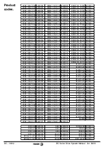
There is an IM card for each correct combination of DCM motor and DCS drive as shown on the
next page. The IM-000 board is used for setting DCS Drives with non-Fagor motors. The
calculation of the passive components is described on the next pages.
The potentiometers accessible from the outside allow a final adjustment of the servo drive system.
The component layout of this card and their functions are described next.
Passive components:
NC: Empty.
RIT: It sets the current value from which the I·T protection starts integrating. If this resistor is
short-circuited, this protection is removed.
RAJFV: When using encoder feedback, it sets the relationship between the frequencies of the
encoder pulses and the equivalent voltage in the internal drive circuits.
RAPT:
The system is protected against motor runaway should it lose feedback. This resistor
sets the overspeed value triggering this protection. The smaller the value of the RAPT the more
tolerant the system is. If short-circuited, this protection will be removed. When working in current
command mode, this RAPT must be short-circuited.
RTV1:
It adapts the voltage generated by the tacho to the internal Drive circuits.
RAD1, CAD1:
They set the derivative compensation at the velocity PI.
RAP1, CAI1:
They set the proportional and integral action of the velocity PI.
Jumpers (in bold, default position):
J1: Feedback type selector. Via encoder (bc). Via tacho (de).
J2: Ramp generator, active (ab), or not (bc).
J3: Activates the acceleration overshooting control. Active (ab).
J4: Selector for the type of command. Current command (ab) or velocity (bc).
Identity Module, IM
Acc/Decc Ramps
Max. Current Limit
PI Gain
Max. Speed
Offset
J3
J4
abcde
ab
abc
J1
abc
J2
NC
RI
T
RA
J
F
V
R
APT
RT
V
1
RA
D
1
CA
D
1
R
AP1
CA
I1
- IM Board -


