background image

®

17 

Obstacle Avoidance


PHASE II 


System Installation Detail Cont’d


Connect Supply & Return Lines


5” EPDM hose couplers are used to make a semi flexi-

ble connection from a SunSaver

®

 bank to Schedule 40, 

2” PVC piping. Below is the best order to follow for con-

necting the supply and return lines: 
1.  Check that all supply lines are connected to the lowest 

end of their collector row and that the upper ends feed 
to a common high point in the system. (as in 

Figure 

5

). 

2. 

Connect 5” couplers on upper and lower inserts of 

all collector corners for supply and return plumb-
ing. Be sure to install hose clamps as depicted in 

Figure 9. 


3.  Route supply line to the bottom header of each row 
4.  Route the return line to the upper header of each 

row. 

5.  If there are straight pipe runs in the plumbing ex-

ceeding 15ft without an offset, there must be either 
a plumbing expansion kit installed or an industry 
standard method to accommodate for any expan-
sion and contraction (see 

Plumbing Layout 

and

 Ap-

pendix C

 for details). 

6.  Both supply and return line plumbing must be 

mounted so that it is allowed to move an equivalent 

of 1/2” for every collector between it and the Fix 

Mounted collector in the bank. If there are multiple 
collectors, it may be advisable to install an Expan-
sion joint immediately in the plumbing so that 
when the bank moves with temperature, the plumb-
ing will be able to absorb the movement immediate-
ly. Refer to 

Plumbing Layout 

and 

Appendix C.


CAUTION: Overtightening Hose Clamps will deform 
connectors and accelerate compression set in de-
formed EPDM hose and will lead to leaking. Torque 
all hose clamps to 35-42 in-lbs. 


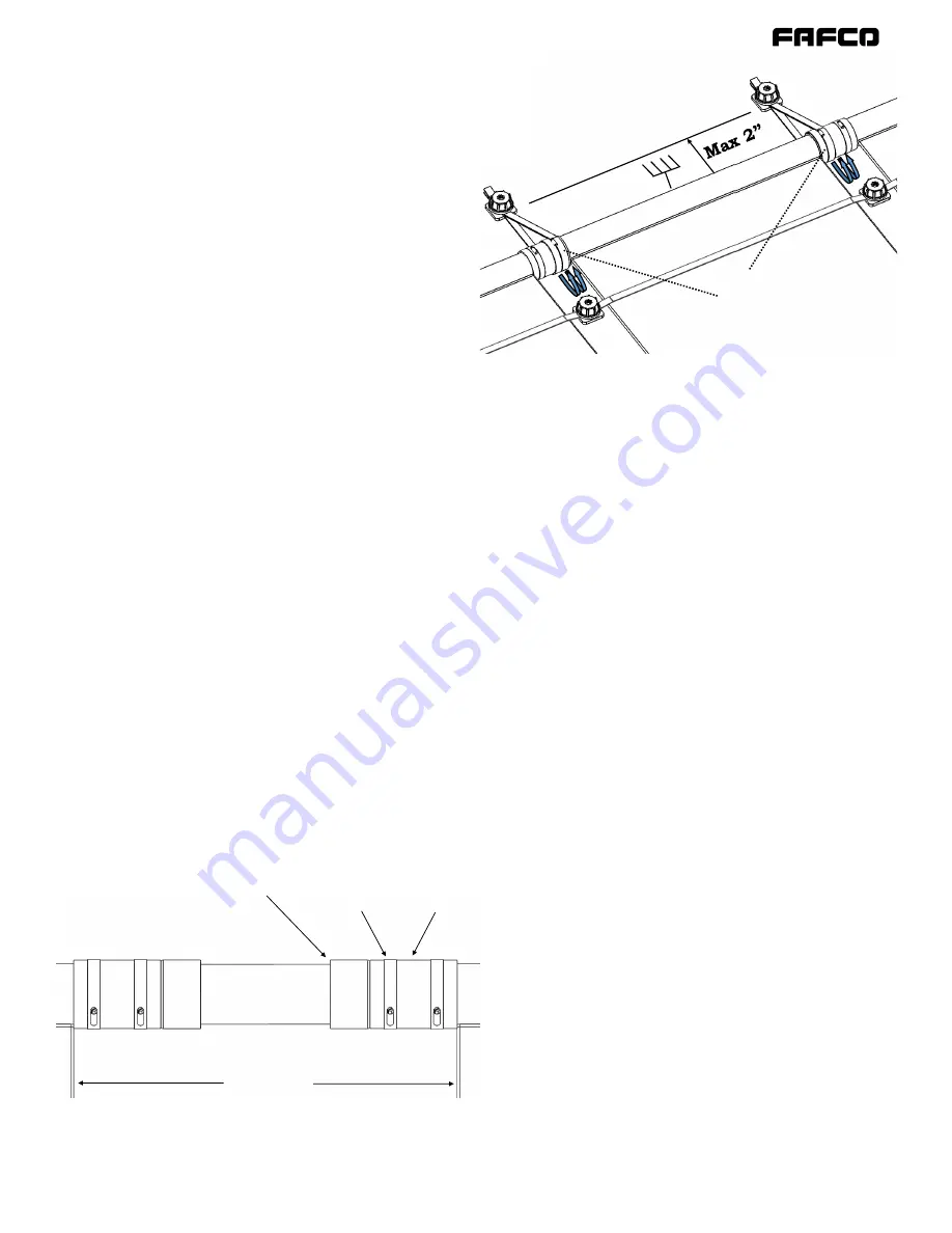
Figure 10 | Adding Space to a Row 

In order to accommodate for obstacles in a row, collectors may need 
to be spaced out by adapting the couplers to PVC. 

Collectors 

PVC Pipe 

Pipe 

Adapter 

Hose 

Clamp 

Coupler 

Since the collectors are made of a polymer that sees 
large temperature swings, there can be a lot of natural 
movement in an array as well as all plumbing. If sim-
ple practices are not adhered to, this natural move-
ment can cause damage to solar collectors, plumbing 
and roof penetrations.  
As seen in 

Phase I

Plumbing Layout 

and 

Appendix C,


SunSaver

®

 banks move both laterally and longitudi-

nally along the roof. It’s often best to mount the mid-

point of the bank so that the movement is divided 
evenly to both sides of the bank. This can be done by 
double wrapping a header strap around the fixed col-
lector on both upper headers and installing the Caps/

Bases up to 2” away from the header (see

 Figure 11

). 

Use a means of fix-mounting this collector which best 
fits the practices of installation company. The plumb-
ing end of the bank will move simply from the move-
ment of the bank which will then translate to the 
plumbing. Since there can be movement translated to 

the plumbing, it’s crucial to plumb the banks so that 

this movement can either be absorbed in the coupler 
or absorbed in the plumbing. To accommodate for 
movement in the banks, all plumbing must be coupled 

to the bank with a 5” coupler and if there is a long run 

of plumbing going directly to the bank, accommoda-
tions for thermal expansion must be utilized. Refer to 
the 

Figures 16 and 20 

in 

Appendix C

.  

Collectors may need to be spaced out to allow for mid-
bank obstacles or changes in roof shape. In most cas-
es, the banks will need to have additional spacing 
added so that the bank can be plumbed around the 

Figure 11|The Fix-Mounted Collector 

On the 

Fix-Mounted Collector

, the upper headers should be double 

wrapped on both sides to keep the Collector as an inflection point of 
bank movement. A means of limiting bank movement should be used 
which best fits the practices of the installation company. 

Double 

Wrap 

(Fixed Points) 

Summary of Contents for Sunsaver

Page 1: ... 1 Made in the U S A S o l a r P o o l H e a t i n g S y s t e m s FOR USE WITH SWIMMING POOLS TO HARNESS THE ENERGY OF THE SUN INSTALLATION MANUAL SUNSAVER ...

Page 2: ...rials Roof Penetrations Hybrid System Layouts PHASE II System Installation Detail Mounting Collectors Connect Supply Return Lines Obstacle Avoidance VRV End Caps Diverter Valve Pool Equipment Tie In Pool Plumbing Thermal System Automation PHASE III Commissioning Diverter Valve Pressure Leak Check Placement of Sensors System Automation Commissioning Documents Installation Manual Table of Contents 4...

Page 3: ...ces Various Plumbing Configurations and High Point Return Plumbing with Balancing Valves No High Point Return Plumbing Movement Bank and Plumbing Movement Appendix D Roof Mounting Details SunSaver Collectors on Composition Roofs SunSaver Collectors on Barrel Tile Roofs SunSaver Collectors on Flat Tile Roofs SunSaver Collectors Wood Rack Mounted SunSaver Collectors Metal Rack Mounted Appendix E Alt...

Page 4: ...O s goal has been to design test and produce the world s highest performing solar pool heating systems Installing a FAFCO solar pool heating system is straight forward and relatively simple This manual pro vides a step by step installation procedure for most applications For those situations not covered in this manual please contact your FAFCO representative Please read this manual completely befo...

Page 5: ...zing Drain at 45 F prior to Freezing Conditions Absorptivity 0 96 Emissivity 0 90 Thermal Specifications Thermal Energy Output 1800 Btu ft2 day System Operating Pressure 100 F At Bottom Header 30 psi System Intermittent Pressure 100 F At Bottom Header 40 psi Factory Test Pressure Burst Pressure Per Collector 50 psi 220 psi Recommended Flow Rate Per Collector 0 1 gal min ft2 Delta T at y intercept ...

Page 6: ... 06918 Black weather resistant polymer Mounts solar collector header and body straps to a roof or rack using a 1 4 lag bolt and cap 7 Cap 06919 Black weather resistant polymer Threads onto base to secure strap 8 21 2 Hose Clamp 02031 Stainless steel 21 2 hose clamp Secures Rubber Couplers to barbed fittings Tighten using flat head or 5 16 socket driver 9 Rubber Coupler 3 1 2 02033 31 2 long 23 8 i...

Page 7: ...ouplers 1 32 header strap 1 2 check valve 1 Owner s Manual 16 Add Bank Pack 154 Adds parts to terminate plumbing and mounting a bank One per added bank of collectors 1 vacuum relief valve 1 CPVC end cap 2 CPVC female adapters 7 tie down caps 7 tie down bases 6 clamps 1 3 1 2 coupler 2 5 couplers 1 32 header strap 17 Split Pack 155 Allows for space around an obstacle one per row space needed 18 Col...

Page 8: ...water remains on shut down 21 3 Way Diverter Valve Enables pool water to be directed to solar or directly to the pool return use in all solar equipped systems 22 Automated Solar Diverter Actuator Enables automatic movement of 3 way diverter valve use with pool automation and pool controllers 23 Pool Check Valve Prevents water from flowing in a reverse direction when unintended use after the pool f...

Page 9: ...ipment Aux Back Up Heater Not Shown Chlorinator Additional Pumps A Figure 3 Diverter Valve Schematic 1 2 3 5 6 7 9 8 11 12 13 15 14 4 16 17 10 Either Tee Upward or Opposing Corner Acceptable Manual Isolation Valve or Check Valve Permitted Optional Figure 2 Example SunSaver System The typical SunSaver solar pool system consists of a combination of FAFCO sourced parts and standard equipment The abov...

Page 10: ...ts The typical SunSaver solar pool system consists of a combination of FAFCO sourced parts and standard equipment The above figure and the component list below depicts common Array Layout Components and shows the proper placement of all components Legend for Figure 4 Array Layout Components SunSaver Collector 4ft wide SunSaver Collector 2ft wide not shown Vacuum Relief Valve End Cap Pipe Adapter B...

Page 11: ... installed under collectors It is typically acceptable to use Schedule 40 PVC for system plumbing In extreme conditions CPVC plumbing may be more applicable See Table 4 in Appendix C Flush out all pipes before connecting them to collectors in order to clear any chips which may have become trapped in the plumbing Systems with local lows in the plumbing should have a way of manually draining the lin...

Page 12: ...g added so that the bank can be plumbed around the obstacle Gaps can be filled by connecting PVC runs to Pipe Adapters and Couplers as depicted in Figure 10 Collector Layout Spacing Collectors and Penetrations Collectors will also grow or shrink along the length of the collector Be sure to mount collectors so that there is at least 2 of clearance from the bottom headers to any obstacles below the ...

Page 13: ...eturn line with a high point will enable a com parable backpressure on the return line of each bank and therefore match collector flow throughout the ar ray Unlike FAFCO CoolPV Systems SunSaver Systems do not utilize an individual high point return line When installing both SunSaver and CoolPV Systems plumbing must conform with the schematics in Figure 8 to ensure the system is properly balanced a...

Page 14: ...rection Two Plumbing Expansion Hoses are advised to accommodate this movement when the plumbing is strapped as shown Refer to Table 6 in Appendix C for recommended Plumbing Expansion Hose lengths In this case the movement in the bank corresponds to 1 2 which can also be transposed to an equivalent of 40ft PVC pipe Table 5 Additionally there is a 10ft line of PVC Adding the two provides 50ft of equ...

Page 15: ...nd pres sure specifications of white PVC by providing documen tation that it conforms to ASTM D1785 or an equivalent standard it should not be used for solar plumbing Due to the poor UV resistant properties of PVC it should be painted upon completion of the installation Plumbing Materials PHASE I Site Preparations Planning Cont d Hybrid System Layouts SunSaver collectors are compatible with most s...

Page 16: ...ding Note It is crucial that the collector couplers and hose clamps are installed properly If improperly positioned the hose clamps and couplers can move and the entire bank of collectors can expand severely under pressure causing the collector body to collide with roof mounted obstacles When installing mounting hardware it is best practice to use the premeasured method mentioned in Collector Layo...

Page 17: ...couplers to PVC Collectors PVC Pipe Pipe Adapter Hose Clamp Coupler Since the collectors are made of a polymer that sees large temperature swings there can be a lot of natural movement in an array as well as all plumbing If sim ple practices are not adhered to this natural move ment can cause damage to solar collectors plumbing and roof penetrations As seen in Phase I Plumbing Layout and Appendix ...

Page 18: ...ectors 2ft wide can be useful on roofs where there are multiple obsta cles to avoid and standard size collectors don t fit 3 Once all collectors have been positioned with clearance finish plumbing the collectors as de scribed in Phase I Mounting Collectors and Con nect Supply and Return Lines 4 After turning on the system ensure the banks have not moved too close to obstacles and address as needed...

Page 19: ... highly recommended that all solar systems be in stalled in conjunction with a pool automation system for optimum system performance Thermal System Automation Pool Plumbing The solar thermal system is installed after the pump and filter but before additional pool equipment Figure 2 Alternatively if pool equipment is specifically la beled by manufacturer as to be installed before the solar equipmen...

Page 20: ...the actuator repositions the valve when directed 2 Check that the set positions direct flow as ex pected Diverter Valve To ensure optimum performance it is highly recom mended to automate all solar thermal systems with an automation package of choice There are many auto mation packages which are available from pool suppli ers such as Pentair Jandy and Hayward It is recom mended by FAFCO to source ...

Page 21: ...rtup for SunSaver solar collectors is essen tially the opposite order of winterizing but also includes checking for leaks and any damage which could have occurred during the winter season Typically a system should be recommissioned for sum mer use whenever ambient temperatures and sunshine is able to produce reasonable heat to exchange with the pool The startup season will vary by location but is ...

Page 22: ...tion Valves Winter OFF Summer ON 7 2 Automation Winter OFF Summer ON 3 Drain Valves Winter Open Summer Closed 1 Figure 13 Solar System Maintenance Figure 13 depicts the components to decommission remove or reinstall during sys tem Winterization Summerization or when performing other routine maintenance ...

Page 23: ... If the collector is still under manufacturer s warranty contact FAFCO to determine replacement eligibility IMPORTANT Attempts to repair SunSaver collec tors by any other means will void FAFCO s Manu facturer s Warranty All repairs are only to be per formed by a FAFCO Authorized installing compa ny Do not attempt to apply screws epoxy or any other types of sealant Collector Repairs NOTE All collec...

Page 24: ...entered between collectors when system is running at operating temperatures The SunSaver system must be capable of draining if not manual drain valves should be installed or a winterization service must be in place All plumbing in the system must hold under pressure without leaking All plumbing in the system utilizes a standard method to allow for thermal movement If used all Flexible PVC lines ar...

Page 25: ...s layout for this system has been attached _____________________________________ Authorized SunSaver Installer Date ___ ___ _____ Pressure Difference ______________________________psi Roof Orientation Circle all that apply for installations across multiple roof pitches N NE E SE S SW W NW A copy of the Dealer s layout for this system has been sketched Home Owner ___________________________________...

Page 26: ...rtical Head Loss ft Head Loss in other Pool Equipment ft Total Head Loss ft Total Head Loss psi Box A Box B Box C Box D Box E Box F Box G Box H Box I Box J Box K Box L Box M Box N Box O Box P Box Q Box R Box U Box S Box T Box V Box W Box X A E B F C G D H I J K L Box P result M N Box Q 5 1 ft ea panel Table A2 from box S T O Pump to top header height R U V W X 0 43 total pipe length used Box Y Los...

Page 27: ...ound to 40 0 028 8 1 Vertical Head Loss ft 24 Head Loss in other Pool Equipment ft 32 14 psi Total Head Loss ft 85 FT Total Head Loss psi 36 PSI Box A Box B Box C Box D Box E Box F Box G Box H Box I Box J Box K Box L Box M Box N Box O Box P Box Q Box R Box U Box S Box T Box V Box W Box X A E B F C G D H I J K L Box P result M N Box Q 5 1 ft ea panel Table A2 from box S T O Pump to top header heigh...

Page 28: ... 28 Example Manufacturer s Pump Curves APPENDIX B Pump Sizing 40 GPM 85FT 40 GPM 85 FT Recommended Pump Speed Curve Recommended Setting ...

Page 29: ...allation Use this table in cases where less than 2 nominal may be needed For example if there is an obstacle on the right of the second collector to the right of the fixed collector 2 collector gaps there should be 1 2 clearance from the obstacle Maximum pressures that CPVC and PVC piping can withstand at higher temperatures Table 4 CPVC vs PVC Temperature F 80 90 100 110 120 130 140 150 160 170 1...

Page 30: ...ine Multi Bank SunSaver Pool Systems utilize a common high point return line enabling each bank to have proportional feed and return line backpressures which limits the water to favor the path of least resistance Notice I is an example of a stacked Reverse Return and II is stacked Same End Return I STACKED REVERSE RETURN II STACKED SAME END RETURN SPLIT FEED REVERSE RETURN ...

Page 31: ... have proportional feed which limits the water to favor the path of least resistance Notice A is an example of a Reverse Return Multi Bank system where the balancing valves are needed and B is a Single Bank Reverse Return which doesn t need balancing valves Similarly C is an example of a Same End Return Multi Bank system where the balancing valves are needed and D is a Single Bank Same End Return ...

Page 32: ...such as an offset should be used so that the line can move as needed Refer to Table 5 for Regular PVC Joint Offset lengths and offset type for a length of pipe Regular PVC Pipe 2X Straight Line Plumbing Fixed Support Guide Supports Fixed Support 4ft Length of Pipe To accommodate for long plumbing runs refer to the table or incorporate an industry standard plumbing offset If space doesn t permit it...

Page 33: ...7 6 0 7 1 8 1 9 2 10 3 11 3 12 4 13 4 Expansion Dimensions Chart for PVC Line Offsets with 3 5 Couplers in Line T 80 F Most Installations Most Installations with Bank Movement Uncommon Installations Length of Pipe ft 10 20 30 40 50 60 70 80 90 100 Thermal Expansion in 0 6 0 8 1 2 1 5 1 8 2 1 2 4 2 7 3 0 3 3 Leg L 4 in 8 7 9 2 9 8 10 4 10 9 11 4 12 0 12 5 13 0 13 5 Leg L 2 in 17 4 18 4 19 7 20 7 21...

Page 34: ...ing movement needed See Table 6 in Appendix C for details It is recommended for the Fix Mounted Collector to be at a the centermost point in a bank as seen in image C of Figure 22 when possible DIAGRAM LEGEND Guide Support Fixed Support Plumbing Expansion Joint Fixed Points 4ft Fix Mounted Collector Bank Moves up to 5X 1 4 2 5 Collector 0 Collector 1 Collector 2 Collector 3 Collector 4 Collector 5...

Page 35: ... recom mended to put a burier between the lower headers and the roof for extra roof protection of the roof when the collectors move with temperature fluctuations Note All mounting hardware must be installed with care Seal all roof penetrations according to an industry standard method NOTE If local codes allow the bolt to be secured only into the sheathing be sure not to overtighten bolts Figure 23...

Page 36: ...e must be used to support the collector from excessive sagging Note All mounting hardware must be installed on a runner and the runner must be mounted into the roof with the same number of penetrations Seal all roof penetrations according to an industry stand ard method Standing Seam Metal Roofs not depicted Mounting substrate and runners fall under the same parameters as in Tile Roof Mounting Roo...

Page 37: ...bstrate is required to support and protect the collec tors from abrasion but may be substituted by a roof rack with support from runners not exceeding 16 separation If the rack has spacing greater than 16 a substrate must be used to support the collector from excessive sagging Figure 25A Tile Stand Off Method Figure 25B Tile Clip Method ...

Page 38: ...if the rack has runners at a minimum spacing of 16 If the rack has spacing greater than 16 a substrate must be used to support the collector from excessive sagging Panels are to be installed no more than 20 vertical feet below pool sur face to the bottom header due to static head pressure at stagnation tem peratures Figure 26 Wood Ground Rack Mounting ...

Page 39: ... if the rack has runners at a minimum spacing of 16 If the rack has spacing greater than 16 a substrate must be used to support the collector from excessive sagging Panels are to be installed no more than 20 vertical feet below pool surface to the bottom header due to static head pressure at stagnation temperatures Figure 27 Metal Ground Rack Mounting ...

Page 40: ...quires Manual Draining To Pool To Solar From Pool To To Solar From Pool To Pool To Solar From Pool To Solar From Pool To Pool SOLAR OFF SOLAR ON SOLAR OFF SOLAR ON Figure 28 DiverterValve on Supply Isolation on Return Aux Heater optional Pool Chlorinator optional Filter Pump Check Valve Diverter Valve Isolation Valves Solar Drain Valves optional Automation Equipment recommended To Solar From Solar...

Page 41: ...m Pool To Pool SOLAR OFF SOLAR ON SOLAR OFF SOLAR ON The below figures depict alternate types and locations of the diverter valve and check isolation valve Non draining configurations should be manually drained for winter self draining systems do not require draining for winterization Aux Heater optional Pool Chlorinator optional Filter Pump Check Valve Diverter Valve Isolation Valves Solar Drain ...

Page 42: ...epict alternate types and locations of the diverter valve and check isolation valve Non draining configurations should be manually drained for winter self draining systems do not require draining for winterization Aux Heater optional Pool Chlorinator optional Filter Pump Check Valve Diverter Valve Isolation Valves Solar Drain Valves optional Automation Equipment recommended To Solar From Solar Inl...

Page 43: ...1 DiverterValve on Return CheckValve on Return The below figures depict alternate types and locations of the diverter valve and check isolation valve Non draining configurations should be manually drained for winter self draining systems do not require draining for winterization Check Valve Isolation Valve Aux Heater optional Pool Chlorinator optional Filter Pump Check Valve Diverter Valve Isolati...

Reviews: