background image

30

Fadal/Sinumerik 810D CNC: Settable Frames - Workpiece Offsets

October 2000

SIEMENS CONTROL

Operator Manual

Fadal

The Work Coordinate System (WCS) - The workpiece coordinate system is
based on the MCS with offsets to shift the workpiece to zero. Workpiece
programming is done in WCS using the workpiece axes designations X, Y,
Z, A and B. The WCS includes all active offsets including the Base Offset,
Settable Work (Zero) Offset and the Tool Offset. 

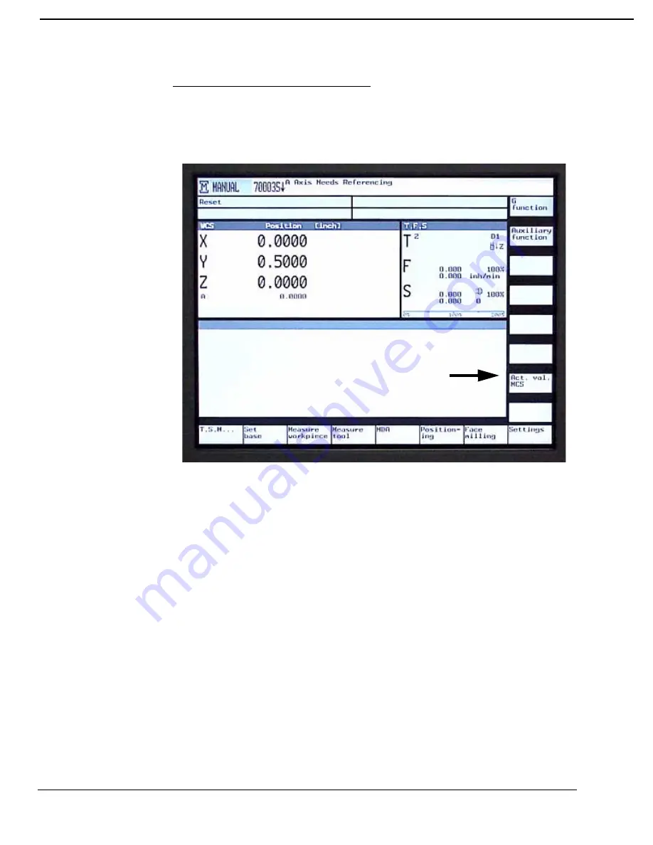
In the MANUAL operating mode it is possible to change between the WCS
and MCS by toggling the Act. Val. MCS soft key.

Summary of Contents for VMC 3020

Page 1: ...SIEMENS CONTROL Operator Manual Fadal...

Page 2: ...28 Settable Frames Workpiece Offsets 29 Machine Coordinate System vs Work Coordinate System 29 Definitions of Offsets 31 Base Offset 31 Zero Offset 31 Tool Offset 31 Using the SET BASE soft key to se...

Page 3: ...Failure to comply with warnings can result in severe injury or material damage Only suitably qualified personnel trained in the setup installation commissioning or operation of the product should wor...

Page 4: ...enever faults occurring in the automation equipment can lead to substantial material damage or even grievous bodily injury i e are potential dangerous faults additional external precautions must be ta...

Page 5: ...th ESD flooring Modules may only be placed on electrically conductive surfaces tables with ESD tops conductive ESD foam plastic ESD packing bags and or ESD transport containers Keep modules away from...

Page 6: ...Tie long hair back and wear protective hair covering to contain long hair 5 USE A NIOSH OR CE APPROVED DUST MASK OR RESPIRATOR Protection is recommended when cutting operations are dusty or exceed th...

Page 7: ...THE MACHINE IN AN UNSAFE ENVIRONMENT Do not use the machine in damp or wet locations or expose to rain Keep the work area well lighted 19 DO NOT FORCE TOOL Tools are designed to perform properly and...

Page 8: ...o the machine when leaving the machine unattended Never leave the machine until it comes to a complete stop 28 DO NOT DISCONNECT THE FRONT DOOR SAFETY SWITCHES 29 WIPE UP SPILLS Immediately cover with...

Page 9: ...VMCs with linear way systems require grease See the Maintenance Manual for specifications on the way lube and the spindle oil 2 Visually inspect the air pressure gauge to verify that it is set to at l...

Page 10: ...ator Manual Fadal 4 Replenish the flood coolant level to avoid running out of coolant during execution of the program 5 Examine the spindle cooler reservoir once a month 6 To power on the machine pres...

Page 11: ...s buttons on the pendant A brief description of the function of each button is given to assist the operator in becoming familiar with the control Refer to the Siemens operator manuals for detailed ins...

Page 12: ...the same time that this button is pressed the main menu of the operator screen is displayed Alarm Acknowledge Resets CNC soft alarms Cursor Buttons left right up down Moves the cursor around the disp...

Page 13: ...lays the offsets screen and offset soft keys menu Page Down Button Page down the screen display Page Up Button Page up the screen display Position Button Displays the position screen and the main soft...

Page 14: ...Toggles the coolant 2 feature on and off Works in combination with M8 and M9 codes Feed Start Button Feed start Slide Start Feed Stop Button Stop feed Slide Hold Increment Jog Button Activates Increm...

Page 15: ...Jog Button Use in conjunction with the JOG and buttons Activates the rapid JOG feed rate Reference Button Activates the Reference submode of the Manual Mode Reset Button Resets the currently active p...

Page 16: ...e NC Cycle Start Button Starts the execution of the CNC in Auto Mode or operation in Manual Mode NC Cycle Stop Button Stops the execution of CNC program control waits for NC Cycle Start signal or Rese...

Page 17: ...axis Select the X axis then press hard key button Select the Y axis then press hard key button Select the Z axis then press hard key button Select the A axis then press hard key button Select the B a...

Page 18: ...18 Fadal Sinumerik 810D CNC Pendant Hard Keys Function Guide October 2000 SIEMENS CONTROL Operator Manual Fadal Note The reference symbol is to the left of the axes names...

Page 19: ...ber 2000 Fadal Sinumerik 810D CNC Operating Modes 19 SIEMENS CONTROL Operator Manual Fadal Operating Modes Manual Data Automatic Submode of Manual display 1 Press the JOG hard key 2 Press the MDA soft...

Page 20: ...20 Fadal Sinumerik 810D CNC Jog Modes Of Operation October 2000 SIEMENS CONTROL Operator Manual Fadal Jog Modes Of Operation Position Readout Display In Jog Mode 1 Press the JOG hard key...

Page 21: ...Jog Using the MPG or JOG Keys Setting the Increment 1 Select the axis to be jogged with the axis selector switch that is located directly to right of the manual pulse generator 2 Select the increment...

Page 22: ...ey This will allow the user to set the jog increment value Using MPG hand wheel 1 Press the MPG hard key button The LED comes on 2 To move the tool in a plus direction turn the manual pulse generator...

Page 23: ...n INCREMENTAL JOG mode 1 Select the axis to be jogged with the axis switch located to the upper right of the manual pulse generator 2 Select the direction to jog the tool using the or hard key buttons...

Page 24: ...to be jogged from the axis selector switch located to the upper right of the manual pulse generator 2 Select the direction of the tool by pressing the or hard key 3 Pressing the RAPID JOG button toge...

Page 25: ...area below the V groove is called the safe zone The safe zone is the only place where the tool holder should be held 2 When unloading a tool from the spindle grasp the tool in the safe zone and press...

Page 26: ...aded into the spindle by using the T S M mode 1 Press the T S M soft key 2 Type T where is the turret location of the tool to be loaded into the spindle 3 Press the INPUT hard key 4 Press the CYCLE ST...

Page 27: ...IDE switch to vary the RPM manually from 50 to 120 of the programmed value M3 CW SPINDLE ON M4 CCW SPINDLE ON M5 SPINDLE OFF M41 LOW BELT RANGE M42 HIGH BELT RANGE CAUTION The last RPM setting used by...

Page 28: ...CW direction 5 Press the CYCLE START hard key to activate Spindle Start After establishing the RPM from T S M Mode or at any time in any mode of operation the spindle can be turned on manually by usin...

Page 29: ...ion COLD START This point is also known as machine zero or machine origin Machine Coordinate System vs Work Coordinate System The Machine Coordinate System MCS The machine coordinate system is based o...

Page 30: ...is based on the MCS with offsets to shift the workpiece to zero Workpiece programming is done in WCS using the workpiece axes designations X Y Z A and B The WCS includes all active offsets including t...

Page 31: ...ero Offsets Fixture Offset 1 8 ZO1 ZO2 ZO8 are programmed via commands G54 G57 and G505 G508 the active ZO example ZO3 is displayed in the light blue field below the axis actual value display Based on...

Page 32: ...Offsets October 2000 SIEMENS CONTROL Operator Manual Fadal The figure below is a two dimensional diagram illustrating the various coordinate systems and their relationship MCS WCS MachineZero Coldsta...

Page 33: ...ith this method The Base Offset for the A and B axes must be set directly in the Zero Offset screen 1 The SETBASE soft key is accessed from the main manual display To get to the display press the MACH...

Page 34: ...on of Offsets October 2000 SIEMENS CONTROL Operator Manual Fadal 5 Jog the X Axis to the desired Base Home position 6 Press the X 0 soft key to set the X Axis base position for the WCS The WCS positio...

Page 35: ...chine will be displayed In the example below the X Axis was jogged to 1 00 The MCS display for the X Axis now shows the Machine Zero Cold Start position is 1 00 inches away from the base position set...

Page 36: ...o get to the display press the MACHINE MANUAL soft key 2 Press the MEASURE WORKPIECE soft key The operator has five options to choose from on the vertical soft keys Edge Corner Hole Spigot and Calibra...

Page 37: ...ition of Offsets 37 SIEMENS CONTROL Operator Manual Fadal 4 Select the Edge soft key when using the X Y and Z WCS position to determine the base setting by using an edge finder or touch probe on the p...

Page 38: ...s October 2000 SIEMENS CONTROL Operator Manual Fadal Note An edge finder or probe can be used for these procedures 5 Select the Corner soft key when setting the WCS base position by determining the or...

Page 39: ...S CONTROL Operator Manual Fadal 6 Select the Hole soft key when setting the WCS base position by determining the center of a hole at four positions 7 Select the Spigot soft key when setting the WCS ba...

Page 40: ...Sinumerik 810D CNC Definition of Offsets October 2000 SIEMENS CONTROL Operator Manual Fadal 8 Select the Calibrate Probe soft key when checking the accuracy of the probe against standards for length o...

Page 41: ...is accessed from the main MANUAL display To get to the display press the MACHINE MANUAL soft key 2 Press the MEASURE TOOL soft key The operator has five options to choose from Length Manual Diameter...

Page 42: ...SIEMENS CONTROL Operator Manual Fadal 5 Select the Diameter Manual soft key when manually setting the tool diameter offset by jogging the tool to a reference block or part 6 Select the Length Auto so...

Page 43: ...sets 43 SIEMENS CONTROL Operator Manual Fadal 7 Select the Diameter Auto soft key when setting the tool diameter offset with a touch probe 8 Select the Calibrate Probe soft key when checking the accur...

Page 44: ...ase and Zero Offsets 1 The ZERO OFFSET soft key is accessed from the main manual display To get to the main manual display press the OFFSET PARAM hard key 2 Press the ZERO OFFSET soft key The zero off...

Page 45: ...perator Manual Fadal 4 The table shows the Base Offset and 4 Zero Offsets at a time Additional Zero Offsets can be viewed by using the PAGE UP PAGE DOWN hard keys as indicated in the display Zero Offs...

Page 46: ...to set the Tool Offsets 1 The TOOL soft key is accessed from the main manual display To get to the main manual display press the OFFSETS PARAM hard key 2 Press the Tool List soft key The Tool List tab...

Page 47: ...xample below the ALTERNATE soft key was used to change the tool type for tool number 1 compare with previous screen display 5 The default setting of the tool list shows the 1st cutting edge To set off...

Page 48: ...the TOOL IN OUT button 3 Place a gauge block of any available size on top of the part 4 Press the MPG button and use the Manual Pulse Generator to jog the Z axis until the tip of the tool is just abov...

Page 49: ...October 2000 Fadal Sinumerik 810D CNC Definition of Offsets 49 SIEMENS CONTROL Operator Manual Fadal...

Page 50: ...ual Fadal Tool Diameter Input To enter tool diameter offsets 1 Press the OFFSET PARAM hard key 2 Press the Tool List soft key 3 Use the cursor keypad arrows cursor down and over to highlight the diame...

Page 51: ...the tool diameter by an incremental value 1 Press the OFFSET hard key 2 Press the Tool Wear soft key 3 Use the cursor keypad arrows cursor down and over to highlight tool length or diameter 4 Type in...

Page 52: ...52 Fadal Sinumerik 810D CNC Definition of Offsets October 2000 SIEMENS CONTROL Operator Manual Fadal Magazine Table Displays active tool and turret location...

Page 53: ...the program Coolant Using the Coolant 1 and Coolant 2 Buttons The coolant buttons can be used to turn the coolant on and off 1 When the flood coolant is off press the COOLANT 1 button to turn the flo...

Page 54: ...ion of Offsets October 2000 SIEMENS CONTROL Operator Manual Fadal 2 When the mist coolant is on press the COOLANT 2 button to turn the coolant off Note Programming M codes M7 Coolant 1 or M8 Coolant 2...

Page 55: ...adal To Create a New Program for Auto 1 Press the PROGRAM MANAGER hard key 2 Press the Program soft key 3 Press the New soft key 4 The operator has the option of using Shop Mill or G code programming...

Page 56: ...n Existing Program 1 Press the Program manager soft key 2 Use the cursor keypad arrows cursor down and over to highlight the program name 3 Press INPUT hard key 4 If the program is in the Shop Mill fo...

Page 57: ...n in Auto Note To choose a program to run in AUTO it must first be active 1 Press the PROGRAM MANAGER hard key 2 Use the cursor keypad arrows cursor down and over to highlight the program name 3 Press...

Page 58: ...adal Auto Running a Program The AUTO button will only execute the currently active program To run the currently active program 1 Press the AUTO hard key 2 Press the NC Cycle Start hard key to begin au...

Page 59: ...of Offsets 59 SIEMENS CONTROL Operator Manual Fadal Mid tape Program Start By using the mid tape start option of the auto command the program can be started from any block The options are available fr...

Page 60: ...gning the axis markers before the referencing procedure is used Alignment can be accomplished by jogging the axes until the markers are in line However these markers can be aligned before the power is...

Page 61: ...erator Manual Fadal Emergency Stop EMERGENCY STOP will cut the power to all axis motors spindle drives and the tool changer To clear an Emergency Stop 1 Release the Emergency stop button 2 Press the R...

Page 62: ...k key a located between the MPG and the TOOL IN OUT hard keys Move Arm Forward The arm will motion forward depending on its previous position Press and hold the SPINDLE STOP d FEED STOP e and CYCLE ST...

Reviews: