


4.6. INFORMATION
The Information screen provides the text information that is configured on the
device from PipeIQ. The fields include Facility name and location, device loca-
tion, and contact person. Use the scroll (
) keys to advance up or down
through the information.
5. EVENT HISTORY
The event history can be viewed through the LCD screen. The Event History
screen displays the event number currently being displayed, the total number
of events available, and the event detail for the currently displayed event. Use
the scroll () keys to advance up or down through the events.
6. MESSAGE LOG
The Message Log history can be viewed through the LCD screen. The Message
Log screen displays the message number currently being displayed, the total
number of messages available, and the message. Use the scroll (
) keys to
advance up or down through the message logs.
7. LCD SETTING
The LCD settings menu allows the user to adjust the language, backlight, and
contrast settings for the LCD. This feature can be locked out and require the
user to enter a 4 digit access code to enter the LCD menu. This four digit
access code is configurable through PipeIQ. When a user selects the LCD Set-
tings menu from the main menu screen with the lock feature enabled, the
enter password screen will be displayed. Once in the settings menu use the
scroll (
) keys to select an option and then select (
) key to confirm
the selection.
7.1. LANGUAGE
The Language screen allows the user to change the language on the LCD.
Languages available:
• English
• Chinese (simplified)
• Chinese (traditional)
• Dutch
• Finnish
• French
• German
• Hungarian
• Italian
• Korean
• Norwegian
• Portuguese (Brazil)
• Portuguese (Portugal)
• Russian (Cyrillic)
• Spanish
• Swedish
7.2 BACKLIGHT
The Backlight screen is used to adjust the brightness of the backlight. Use the
scroll (
) keys to increase and decrease the backlight brightness. Press the
Enter key to register the new setting.
7.3. CONTRAST
The Contrast screen is used to adjust the contrast of the text. Use the scroll
(
) keys to increase and decrease the contrast.
7.4. DISPLAY TIME OUT
The Time Out information set for the unit is displayed.
8. DIAGNOSTIC
Information on system diagnostics is displayed.
MODES OF OPERATION
INITIALIZATION
When the FAAST XS system is initially powered up it is not configured, a
fault indication is set with the General Fault LED and the LCD home screen
displaying a configuration fault. This will indicate that the device has not had
its initial configuration loaded and will remain in this fault state until a valid
configuration has been sent to the device. Upon reconfiguration, the device
9 ASUG80001
will perform an initialization. This initialization will reset the air flow baseline
and the filter clogged baseline. It is important that the system has been con-
nected properly to the pipe network and the filter is installed properly when
the device is initialized as these baselines will be used to indicate when a fault
should occur. During the initialization period the device will operate normally
Accurate Flow and filter statuses will not display until the baseline is set. Es-
tablishing the baseline takes approximately five minutes.
CONFIGURATION OVERVIEW
FAAST XS is configured using PipeIQ. Data is sent via a built in Ethernet
connection or through the USB interface located in the wiring cabinet of the
device. The device will validate the configuration before the configuration be-
comes active. After validation of the data the device will perform an initializa-
tion with the new configuration. If there is a problem with the configuration
data the device will indicate a Configuration Fault on the user interface and
set the Fault relay. The device will require a new configuration before operat-
ing properly.
FAN SPEED CONFIGURATION
The device is capable of running at 3 different fan speeds. To minimize power
the lowest fan speed that meets the requirements should be selected. The fan
speed directly affects the performance of the device. Likewise, pipe network
calculations performed in PipeIQ are based on the fan setting. If the fan setting
is changed on the device at a later date the pipe system must be re-verified.
ALARM AND RELAY CONFIGURATION
Alarm thresholds are set to default levels when shipped, but are configurable.
Each Alarm level has its own set of form C relay contacts. As the particulate
level crosses the threshold for the alarm level the corresponding indicator will
illuminate and the relay will activate. The Alarm thresholds and their associ-
ated relay outputs are configurable for latching or non-latching operation For
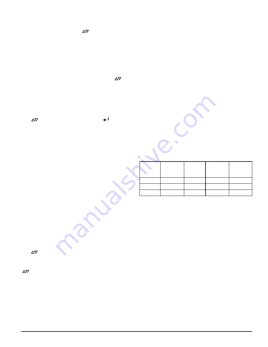
each alarm level, there is a configurable delay from 0 to 60 seconds. Configu-
rable thresholds for each alarm level are as follows:
TABLE 5. PROGRAMMABLE ALARM LEVELS
ALARM
LEVEL
DEFAULT
THRESHOLD
%OBS/FT
PROG.
RANGE %
OBS/FT
DEFAULT
THRESHOLD
%OBS/M
PROG.
RANGE
%OBS/M
Alert
0.012
0.00029 - 6.25 0.0396
0.00095 - 20.0
Fire1
0.250
0.00029 - 6.25 0.825
0.00095 - 20.0
Fire2
0.500
0.00029 - 6.25 1.65
0.00095 - 20.0
AUDIBLE INDICATOR CONFIGURATION
There is an integrated audible indicator on the FAAST XS which provides the
option to include a supplementary audible indication of alarms and faults.
The settings are configurable using the PipeIQ software. The sounder is ca-
pable of generating a pulsed or continuous tone. Both the alarm and fault can
be selected to do either tone.
POWER GLITCH DURING CONFIGURATION
During an upload of configuration data, the device will keep the last known
valid configuration in memory until a complete validation is done on the new
configuration data. This prevents device corruption in the event of a power
loss or network failure. After power has been restored the device will initial-
ize with the last known good configuration. The device will also indicate a
Configuration Fault on the user interface and set the Fault Relay. This will only
occur once. After the next Reset or Power-on-Reset the device will continue to
use the last known good configuration.
NORMAL
In Normal operating mode the FAAST XS displays the air flow and current
particulate levels on the user display. The time, date, address, and current
obscuration is shown on the LCD. The particulate level is compared to the
threshold levels programmed into the device and will activate the appropri-
ate alarm as the particulate exceeds that threshold. If any fault occurs it will
activate the fault LED and display the type on the LCD as well as set the cor-
responding relay.
TEST
Test mode is initiated through the PipeIQ Live View tab or through the LCD in-
terface. Test mode will simulate a fire condition by activating all ten segments
in the Particulate Level display and each segment in the Alarm display. Each
corresponding alarm relay will also activate after any programmed delay asso-


